Yes. The complete plan is available to read on this page.
THE FREE BUILD GUIDE
Tin Door Cabinet
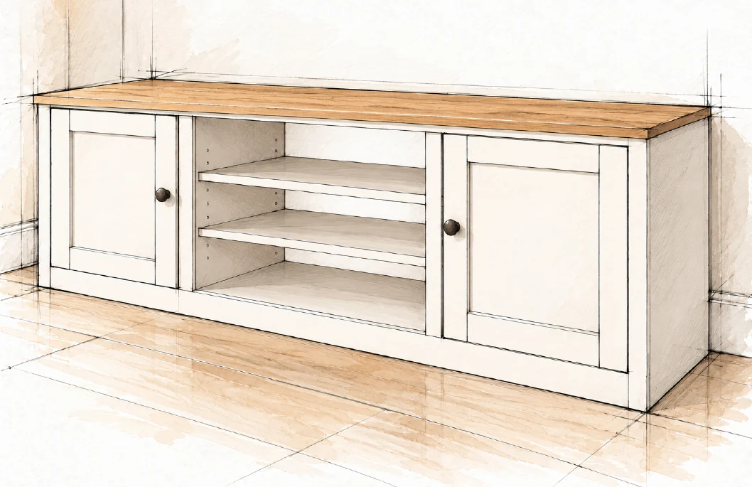
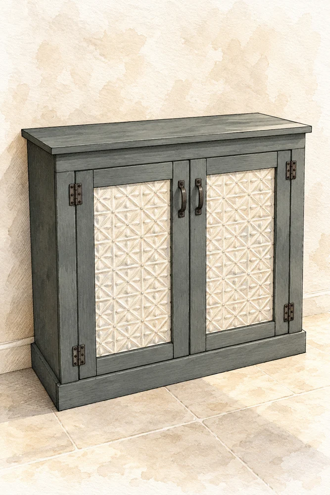
A two-door cabinet with fixed shelves and framed faux-tin panels.
01 / PLAN THE BUILD
Know the cabinet
Read the full guide before cutting. Inches are the working dimensions; metric values are reference conversions.
The construction
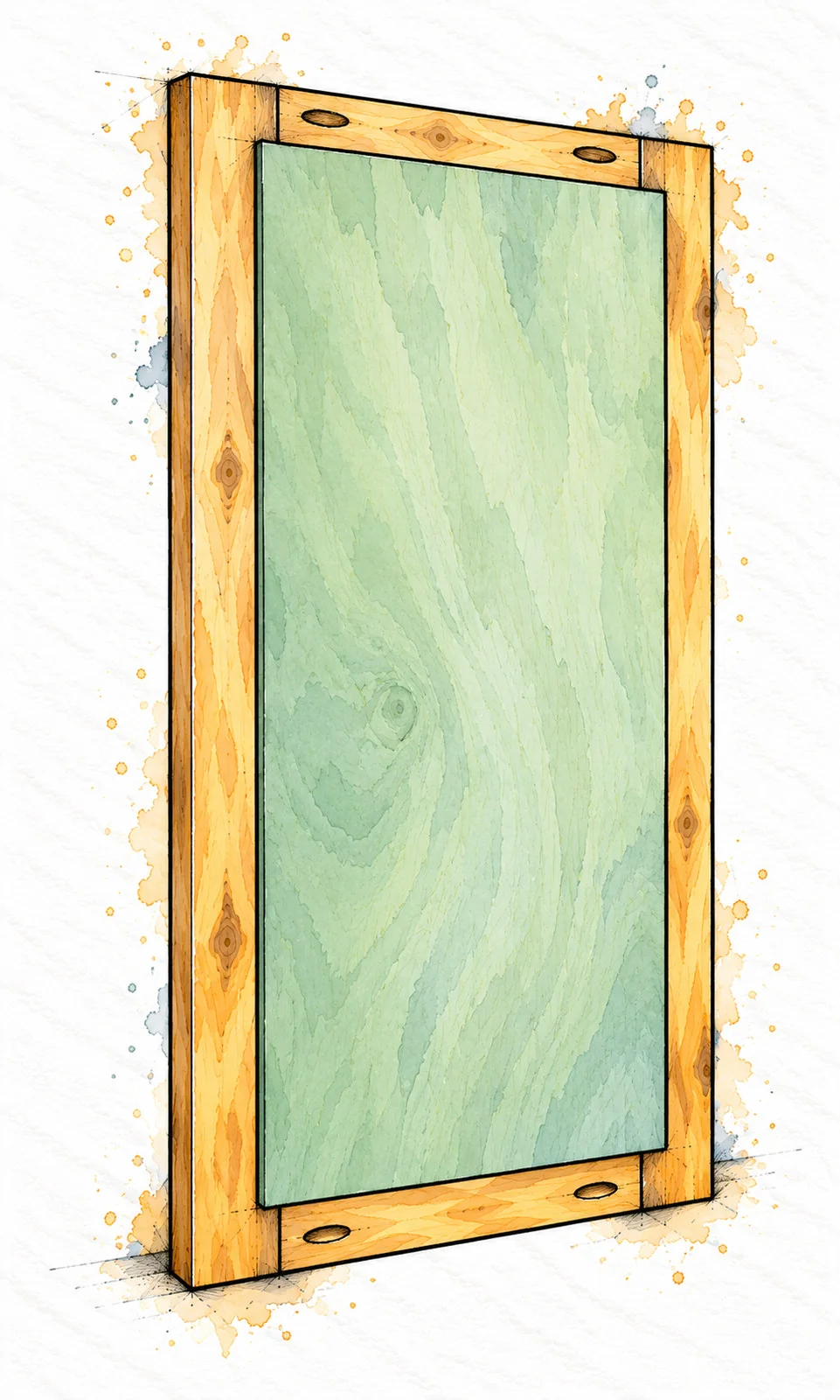
A plywood box carries the shelves and top. A solid-wood face frame and base wraps cover the front and lower edges. Two inset doors use thin faux-tin sheets bonded to plywood backing, not structural metal.
Finished size
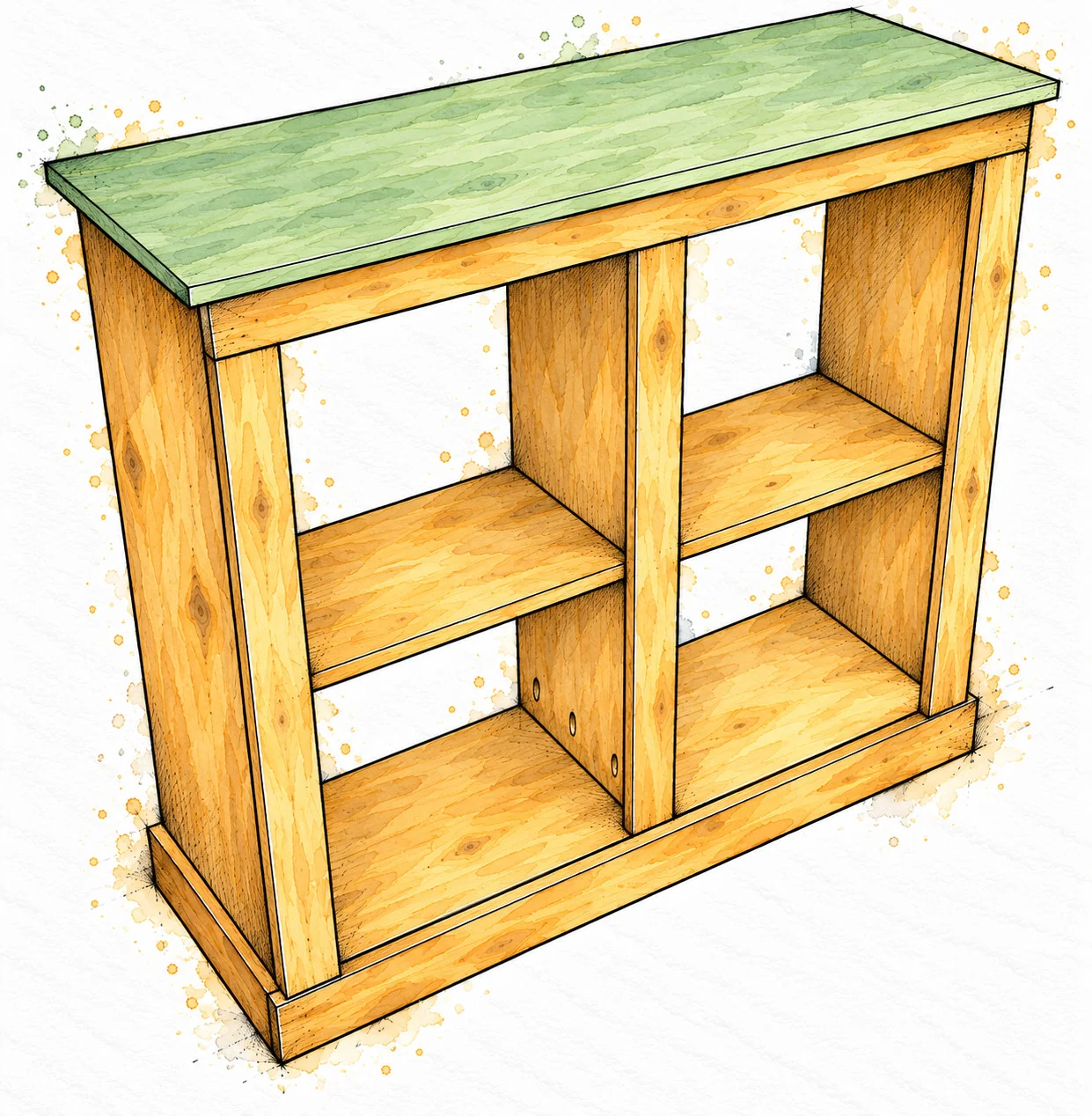
The top is 41 × 14 in (1041.4 × 355.6 mm). With a 3/4 in (19.1 mm) top over 38 in (965.2 mm) sides, the finished height is 38 3/4 in (984.3 mm).
Do not confuse body depth with overall depth
12 3/4 in (323.9 mm) is the side-panel depth plus the front face frame. It excludes the top and back. Use the 14 in (355.6 mm) top depth when checking the cabinet footprint.
Fit parts to the actual build
Choose compatible inset-door surface hinges before final door sizing. The nominal cut list assumes true 3/4 in stock and standard dressed 1× boards. Measure real thicknesses and dry-fit before glue.
How to read the illustrations
The 17 workshop views follow the build sequence. Ink-and-wash drawings show assembly, not scale. Colors distinguish parts and are not required finish colors. Use the dimensions and checks, never the image size.
02 / BEFORE THE FIRST CUT
Materials
Inspect panels for flatness and boards for straight grain, twist and damaged ends.
Panels and boards
• 1 sheet 3/4 in hardwood plywood, 4 × 8 ft • 1 sheet 1/4 in hardwood plywood, 4 × 8 ft • 2 nominal 1×3 boards, 8 ft long • 2 nominal 1×3 boards, 6 ft long • 1 nominal 1×4 board, 6 ft long
Top and decorative inserts
Cut the top from the 3/4 in plywood sheet and finish exposed edges with thin iron-on edge banding. Do not add thick trim that changes its 41 × 14 in size. Buy enough thin, flexible faux-tin sheet for both door inserts; match its pattern before cutting.
Fasteners and consumables
• 1 1/4 in (31.8 mm) pocket-hole screws for 3/4 in stock • 1 1/4 in (31.8 mm) brad nails for frame and trim joints • Panel staples or brads sized for the back and door backers • Wood glue, compatible hot glue and edge banding • Sanding abrasives, filler and compatible paint or stain
Purchase quantities
Fastener counts and finish coverage are not fixed. Select screws for your plywood and jig. Panel fasteners must pass through 1/4 in (6.4 mm) backing and grip the frame without breaking through the visible face.
03 / PREPARE THE WORKSHOP
Hardware tools and safety
Hardware to select before door cuts
Use 4 surface-mounted hinges compatible with inset 3/4 in doors and 2 pulls. Check the hinge manufacturer’s required reveal, screw size and swing clearance on a scrap mock-up. Include a cabinet anti-tip restraint with fixings matched to the wall structure.
Measuring and cutting
Tape measure, pencil, square and straightedge; miter or crosscut saw; suitable plywood-ripping saw and guide, or a supplier cutting service. Support both sides of every panel cut on a stable surface.
Assembly and finish tools
Drill/driver and correct bits; pocket-hole jig for measured stock thickness; clamps; brad nailer or stapler; hot-glue gun; suitable scissors or shears for the selected faux tin; sander and dust extraction. Follow each tool’s instructions.
Protect yourself
Wear eye and hearing protection and suitable dust protection. Keep hands clear of blades and fastener paths. Disconnect power or air before adjustments. Do not hold a small part by hand while cutting or nailing it.
Heat finish and lifting
Hot glue and the edge-banding iron can burn skin. Use a heat-resistant work area. Ventilate when finishing and follow product drying and disposal directions. Get help turning or carrying the cabinet.
04 / ACCURATE MEASUREMENTS
Stock sizes and panel cuts
Nominal lumber names are not finished dimensions. Measure all stock before setting the jig or cutting fitted parts.
Part
Size and use
1×3 3/4 × 2 1/2 19.1 × 63.5
1×4 3/4 × 3 1/2 19.1 × 88.9
Plywood 3/4 or 1/4 thick 19.1 or 6.4 thick
Plywood may be thinner than its label. All measurements below assume the stated thickness. 4 × 8 ft = 48 × 96 in (1219.2 × 2438.4 mm).
Part
Size and use
A
Sides × 2 38 × 12 965.2 × 304.8
B
Base × 1 38 × 12 965.2 × 304.8
C
Divider × 1 34 1/2 × 11 1/4 876.3 × 285.8
D
Shelves × 2 18 5/8 × 10 3/4 473.1 × 273.1
E
Top × 1 41 × 14 1041.4 × 355.6
Parts A-E use 3/4 in plywood. Mark each part and its front edge immediately after cutting. Allow for saw kerf and end trimming.
05 / FINISH THE CUT LIST
Frame and backing cuts
Part
Size and use
H
Face stiles × 2 1×3 32 812.8
I
Top header × 1 1×3 39 1/2 1003.3
J
Front base × 1 1×4 41 1041.4
K
Side bases × 2 1×4 12 304.8
L
Door stiles × 4 1×3 31 3/4 806.5
M
Door rails × 4 1×3 12 1/16 306.4
N
Center facing × 1 1×3 34 1/2 876.3
1/4 in plywood Size in Size mm
F Cabinet back × 1 39 × 35 1/4 990.6 × 895.4
G Door backers × 2 28 1/2 × 13 9/16 723.9 × 344.5
N is the narrow front facing of the center divider, not an extra shelf or loose brace. Final door and backer sizes must be checked against the assembled openings and chosen hinges.
06 / CHECK BEFORE CUTTING DOORS
Layout and fit checks
Keep enough stock
Each 8 ft 1×3 can yield one 32 in stile and two 31 3/4 in door stiles: 95 1/2 in (2425.7 mm) before saw kerf. This is a tight layout. Measure usable length and blade kerf first; use longer stock if end trimming prevents these cuts.
Use the two 6 ft boards
From one 6 ft 1×3, cut the 39 1/2 in header and two 12 1/16 in rails. From the other, cut the 34 1/2 in center facing and two rails. The 1×4 yields the 41 in front base and two 12 in side bases. 6 ft = 72 in (1828.8 mm).
Expected clear opening
The cabinet is 39 1/2 in (1003.3 mm) wide before side base wraps. Two 2 1/2 in face stiles leave a 34 1/2 in (876.3 mm) wide opening. The opening is 32 in (812.8 mm) high. Check its width at top, middle and bottom.
Door size and reveal
Each standard door is 17 1/16 × 31 3/4 in (433.4 × 806.5 mm). Together, the doors leave 3/8 in (9.5 mm) across the opening, nominally three 1/8 in (3.2 mm) gaps. Height leaves 1/8 in above and below. Hinge requirements take priority over these calculated gaps.
One measurement system
Metric values use exactly 25.4 mm per inch, rounded half-up to 0.1 mm. Do not accumulate rounded metric dimensions within a joint. Cut with one system and verify the actual fit.
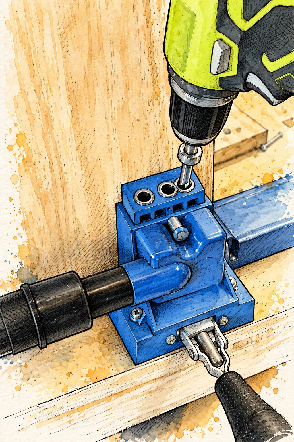
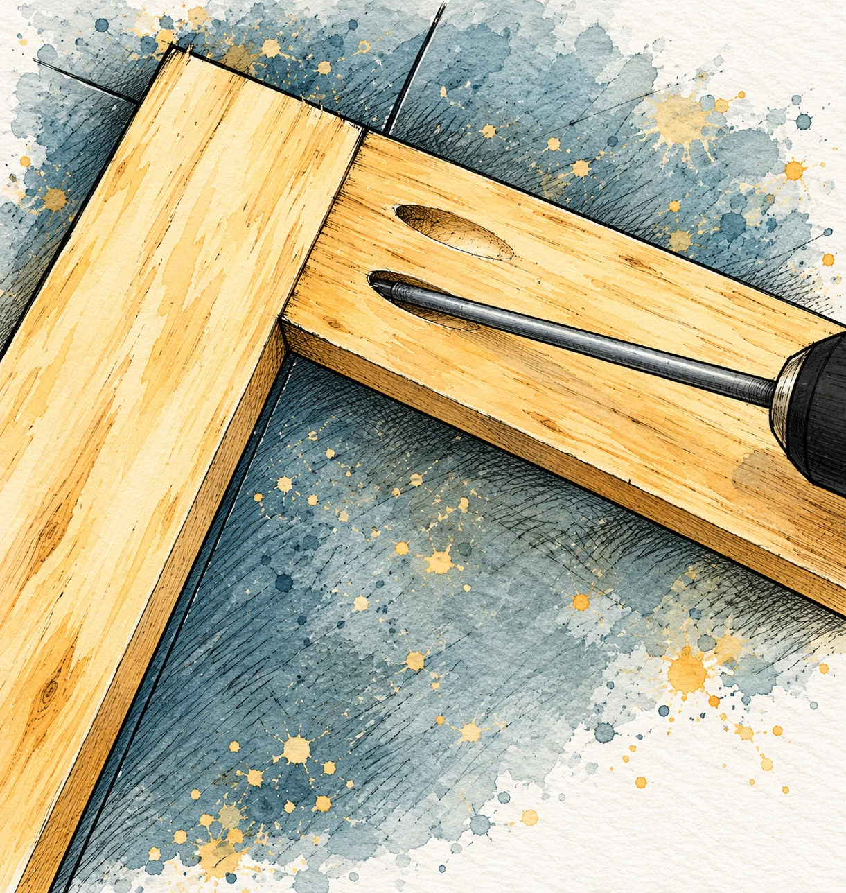
WORKSHOP VIEW 01 / PREPARE THE CARCASS
Pocket holes in plywood
Pocket holes in plywood · Tin Door Cabinet
Set the jig
Measure the plywood, then set the jig and drill stop for that thickness. For the planned stock, use the 3/4 in (19.1 mm) setting. This is the material setting, not the diameter of the hole.
Drill before access is blocked
Clamp the work firmly. Drill base-end pocket holes to join the sides, and upper side-panel holes for attaching the top later. Follow the jig directions and test one joint on an offcut.
CHECK BEFORE MOVING ON
Keep pocket holes on concealed faces. The test screw must not break through the receiving piece.
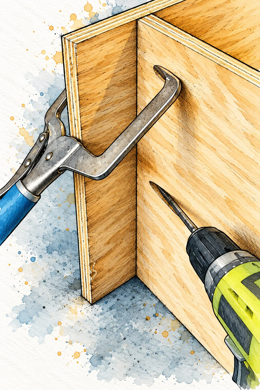
WORKSHOP VIEW 02 / SQUARE JOINTS
Clamp the base joint
Clamp the base joint · Tin Door Cabinet
Make a flush butt joint
Dry-fit the base between the side panels. Clamp the joint at a right angle with the edges aligned. Apply a thin, even layer of wood glue to the mating surfaces.
Drive without shifting
Use 1 1/4 in (31.8 mm) pocket-hole screws and the correct driver bit. Keep the clamp in place until the joint is secure; stop when the head seats rather than crushing the pocket.
CHECK BEFORE MOVING ON
Keep fingers away from the screw path. The two panels must meet without a gap or sideways offset.
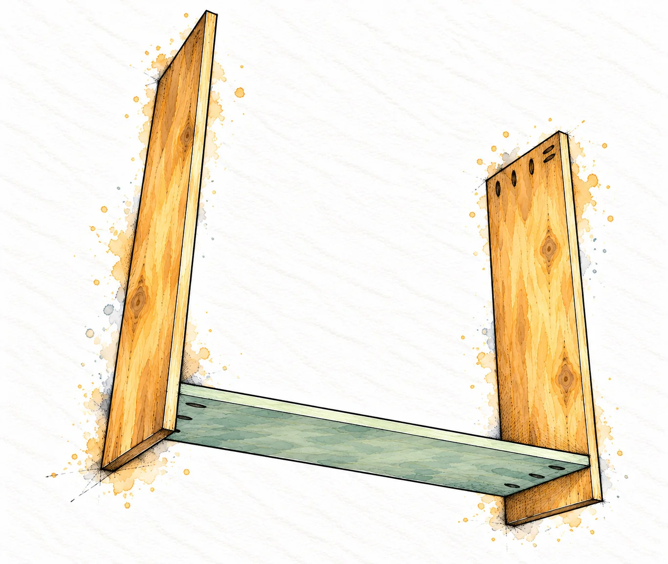
ASSEMBLY 01 / SIDES AND BASE
Assemble the cabinet box
Assemble the cabinet box · Tin Door Cabinet
Locate the base
Mark the underside of base B at 2 3/4 in (69.9 mm) above the bottom of each side A. With 3/4 in stock, the base top will be 3 1/2 in (88.9 mm) above the floor.
Join both ends
Glue and pocket-screw B between the sides with 1 1/4 in screws. Keep front and rear edges aligned. Use a square at each corner and temporary clamps while the glue sets.
CHECK BEFORE MOVING ON
The outside width is 39 1/2 in (1003.3 mm). Both side bottoms and tops must align.
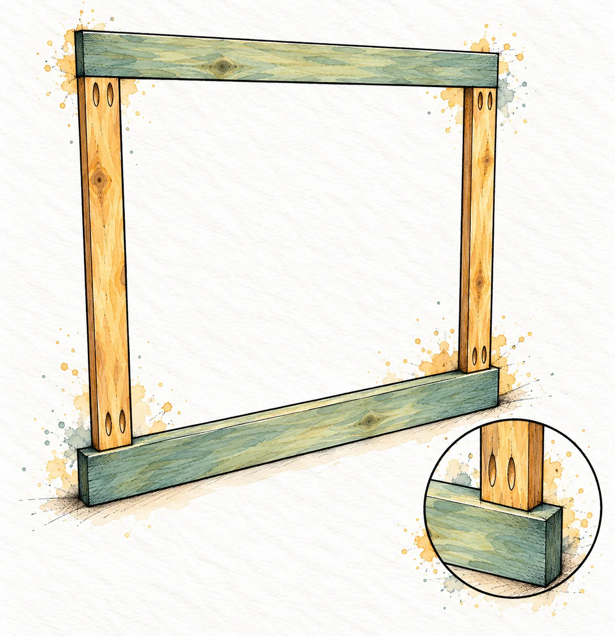
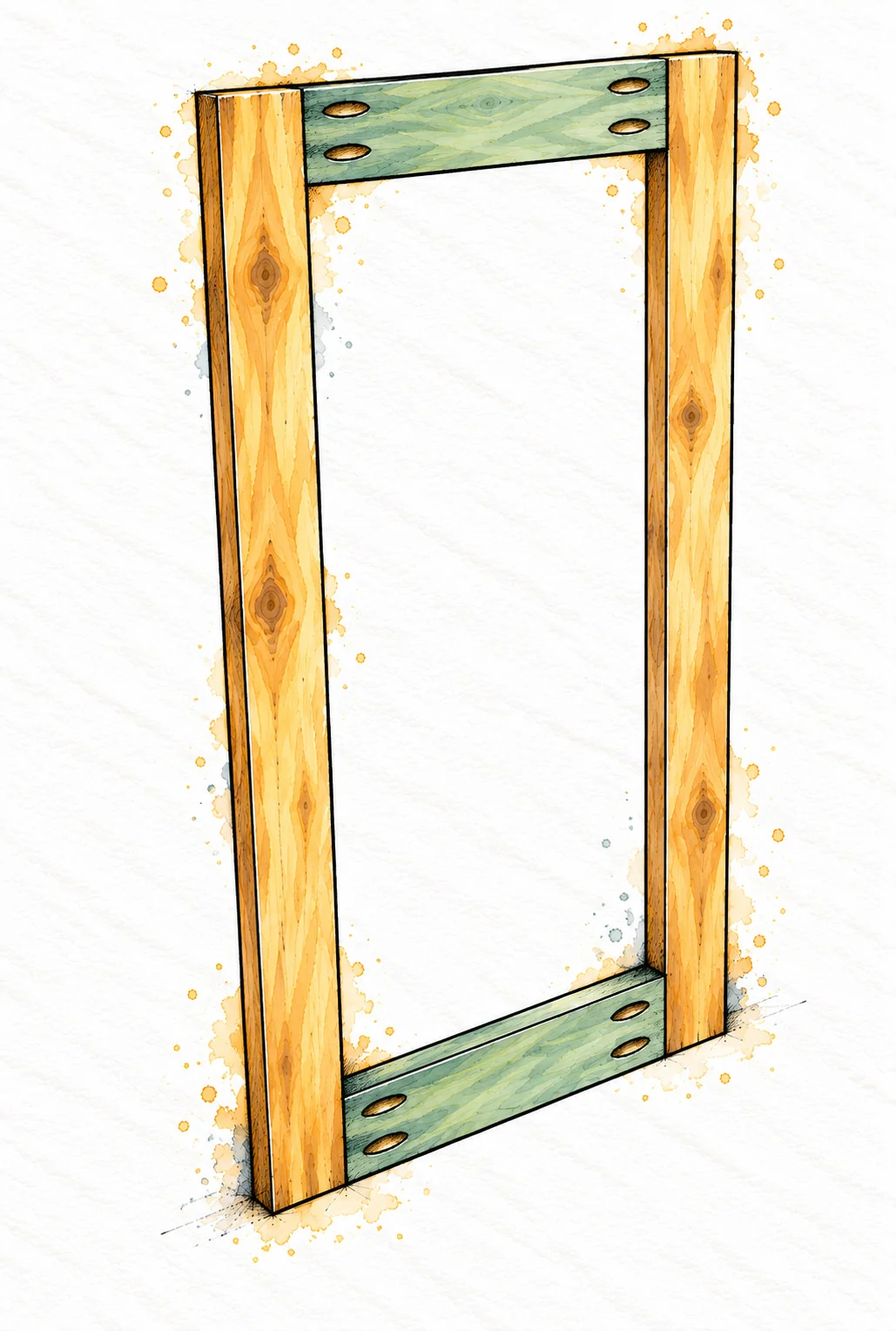
ASSEMBLY 02 / HEADER STILES AND BASE
Build the outer face frame
Build the outer face frame · Tin Door Cabinet
Lay out the frame flat
Place two H stiles between header I and front base J. The header is flush with the outer stile edges. The 41 in base extends 3/4 in (19.1 mm) beyond each stile.
Join the four corners
Drill pocket holes in the stile ends on the back face. Glue, clamp the faces flush and use 1 1/4 in pocket-hole screws. Keep the 32 in (812.8 mm) opening height consistent.
CHECK BEFORE MOVING ON
Compare both diagonals. The inset shows the base overhang, not a notch or a miter.
ASSEMBLY 03 / COVER THE CARCASS EDGES
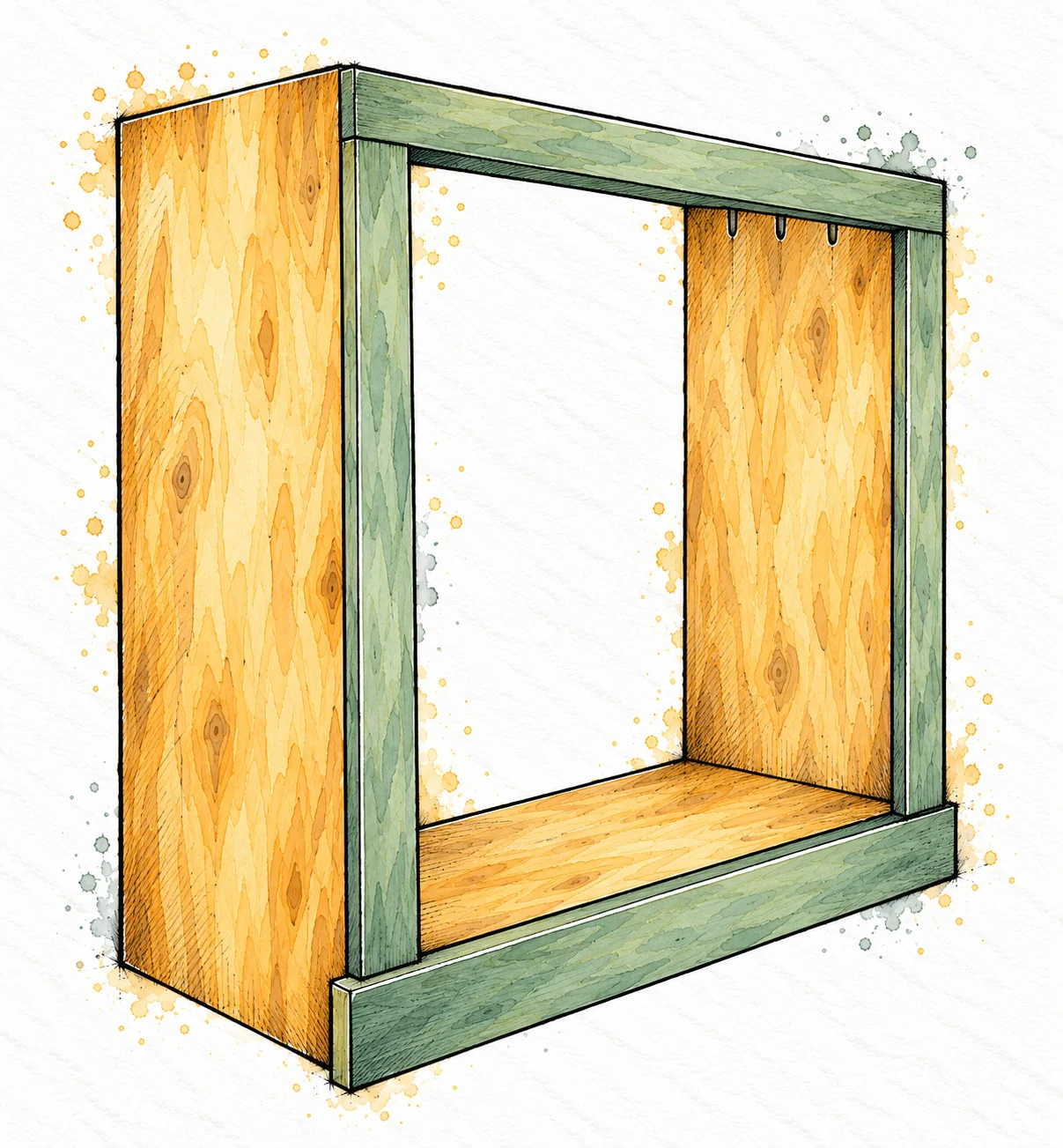
Attach the face frame
Attach the face frame · Tin Door Cabinet
Align before fastening
Apply glue along the front edges of the sides and base. Set the outer face frame on the cabinet with its top and outer stiles aligned to the carcass.
Clamp then nail
Clamp securely and attach with 1 1/4 in (31.8 mm) brads. Aim into the plywood edges and keep every nail clear of existing screws. The front base projects equally at both ends.
CHECK BEFORE MOVING ON
The top and both sides remain square. Wipe away glue squeeze-out before it hardens.
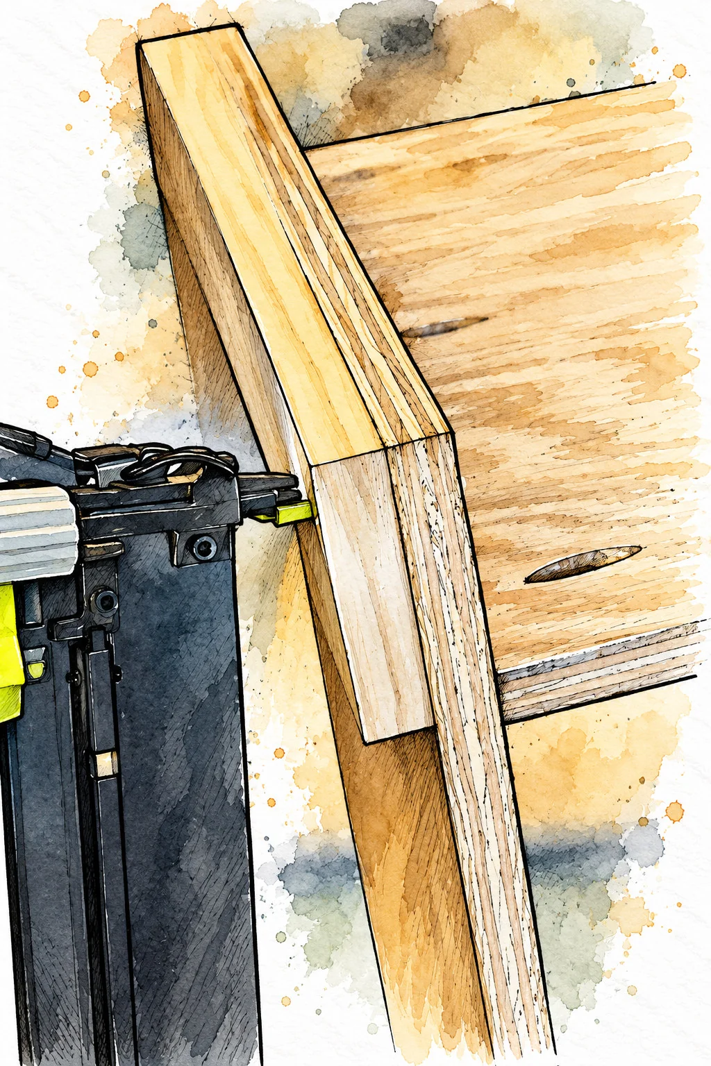
WORKSHOP VIEW 06 / FACE FRAME CLOSEUP
Control the brad path
Control the brad path · Tin Door Cabinet
Mark the hidden edge
Use light pencil marks to show where the plywood edge lies under the face frame. Keep the nailer nose square to the work and follow its contact-safety instructions.
Stay out of the exit zone
Clamp instead of holding the joint near the nailer. A brad can deflect through a narrow plywood edge. Check both sides after each fastening run and remove any protruding fastener safely.
CHECK BEFORE MOVING ON
Glue and clamps establish alignment. The brads hold the joint while the glue cures.
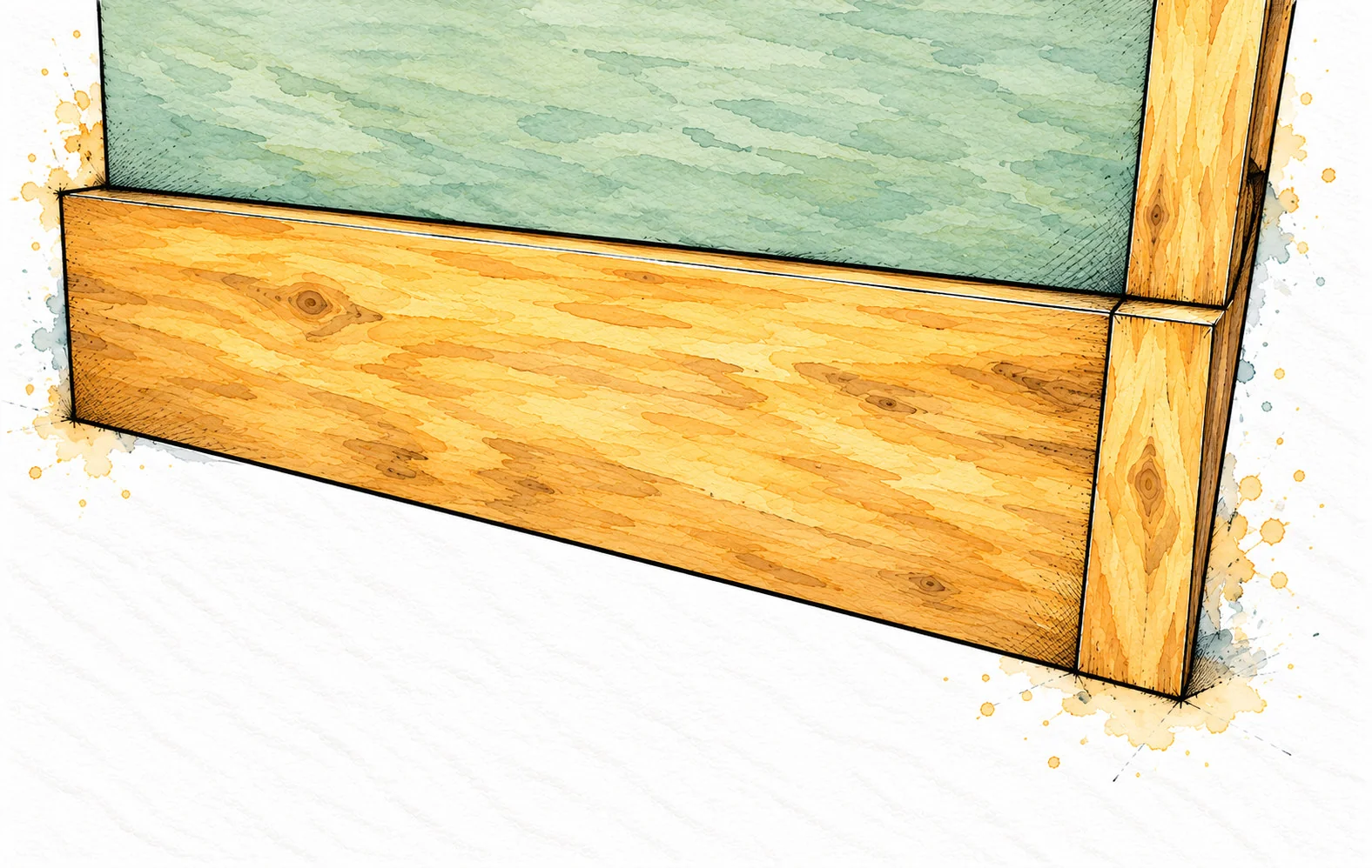
ASSEMBLY 04 / SIDE BASE TRIM
Wrap the lower sides
Wrap the lower sides · Tin Door Cabinet
Fit the two side bases
Place each 12 in (304.8 mm) K piece along the bottom of a side panel. Its front end butts against the projecting end of front base J; it does not overlap the front rail.
Glue and secure
Keep the lower edges flush. Apply wood glue, clamp the trim and use 1 1/4 in (31.8 mm) brads into the side panel. Repeat on the other side.
CHECK BEFORE MOVING ON
Both corner joints close cleanly. The front base and side wraps share the same bottom line.
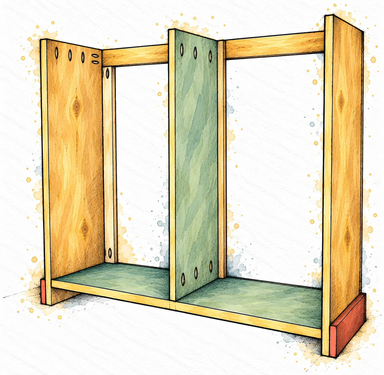
ASSEMBLY 05 / TWO EQUAL BAYS
Fit the center divider
Fit the center divider · Tin Door Cabinet
Dry-fit the center assembly
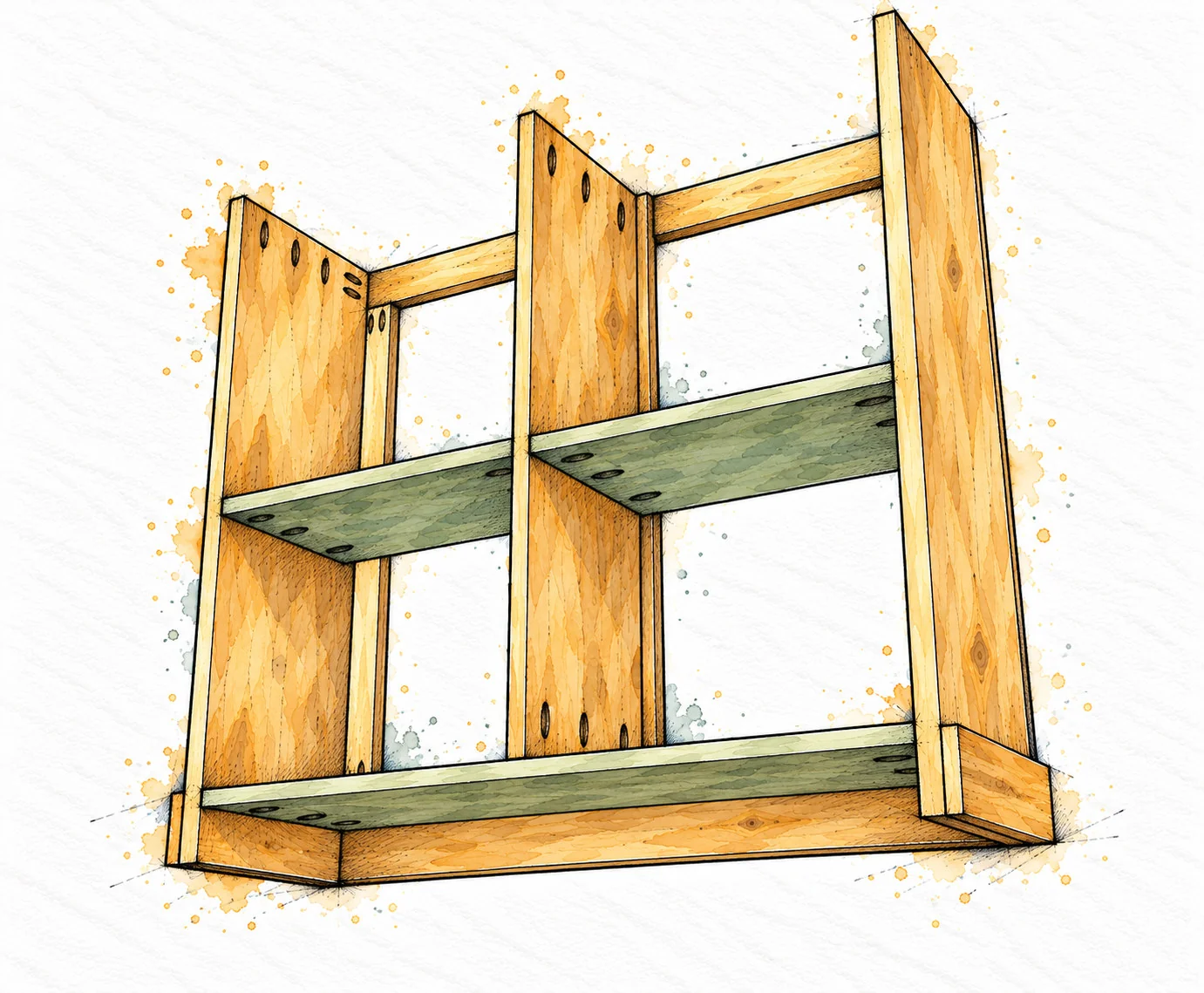
Center facing N on the front edge of divider C, with their tops and bottoms aligned. Together their depths equal 12 in (304.8 mm). Dry-fit with the facing behind the outer face frame and the divider rear flush with the sides.
Secure at the center
Center C on the base so both bays are 18 5/8 in (473.1 mm) wide. Glue and use 1 1/4 in pocket screws into the base. Glue and use 1 1/4 in brads at the divider’s front-facing and upper face-frame contacts.
CHECK BEFORE MOVING ON
The center facing rises behind the top header. Keep it centered; do not add a second center strip.
ASSEMBLY 06 / CHOOSE USEFUL HEIGHTS
Install both shelves
Install both shelves · Tin Door Cabinet
Choose the positions
Mark shelf heights to suit what you will store. The illustrated height is only an example. Mark matching level lines on each side and the divider, then test the shelf fit.
Fasten the shelves
Drill pocket holes underneath both ends of each D shelf. Apply glue, support each shelf level and use 1 1/4 in (31.8 mm) pocket screws into the side and divider. Keep the rear edges aligned.
CHECK BEFORE MOVING ON
Each shelf is 18 5/8 × 10 3/4 in (473.1 × 273.1 mm). Do not force an oversize shelf into a bay.
ASSEMBLY 07 / ONE FLAT PANEL
Attach the plywood top
Attach the plywood top · Tin Door Cabinet
Prepare the edges
Cut E to 41 × 14 in (1041.4 × 355.6 mm). Apply thin edge banding to exposed plywood edges, trim it flush and smooth it. Keep the top flat while working.
Position and screw
With help, place the cabinet upside down on the protected underside of E. Center it left to right and check the front and rear overhangs. Use 1 1/4 in pocket screws through the prepared upper carcass holes into the top.
CHECK BEFORE MOVING ON
Test screw length on scraps first. No tip may break through the visible top surface.
ASSEMBLY 08 / CLOSE THE CABINET
Square and fit the back
Square and fit the back · Tin Door Cabinet
Check the diagonals
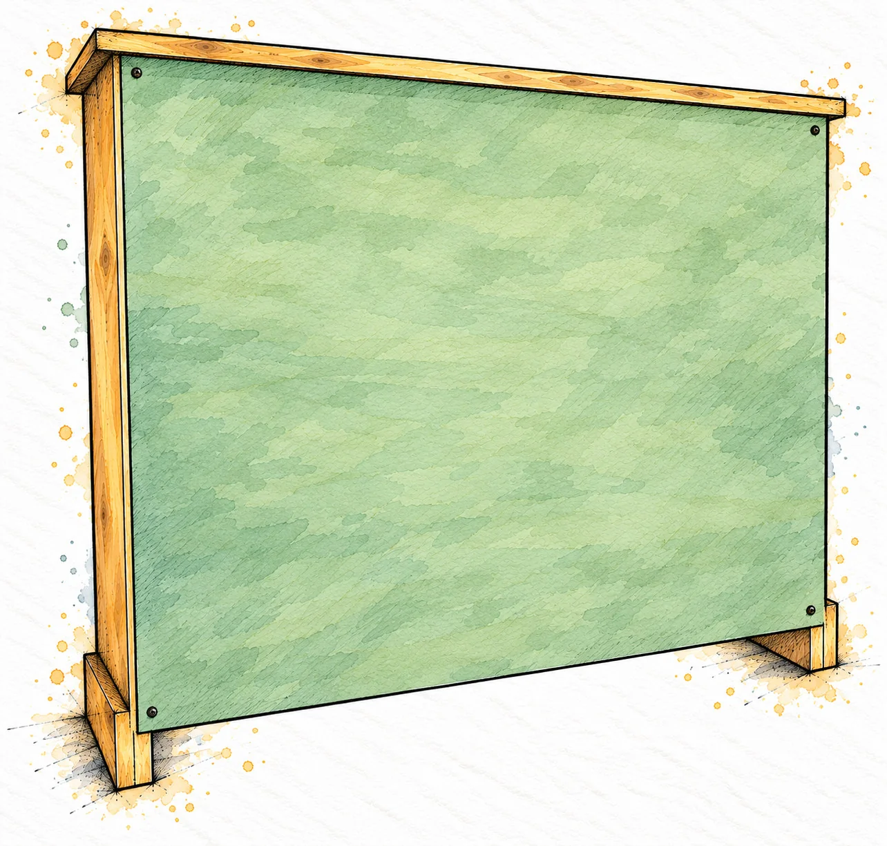
Lay the cabinet safely face down on padded supports. Check corner-to-corner diagonals and adjust the box square before attaching the back.
Attach panel F
Fit the 39 × 35 1/4 in (990.6 × 895.4 mm) back with its top at the carcass top and its sides evenly inset. Staple or brad-nail into the cabinet edges. Choose fasteners that grip without emerging through visible faces.
CHECK BEFORE MOVING ON
Recheck squareness while fastening. The back must lie flat without bowing or loose edges.
WORKSHOP VIEW 12 / FOUR PIECES PER FRAME
Lay out both doors
Lay out both doors · Tin Door Cabinet
Measure the opening again
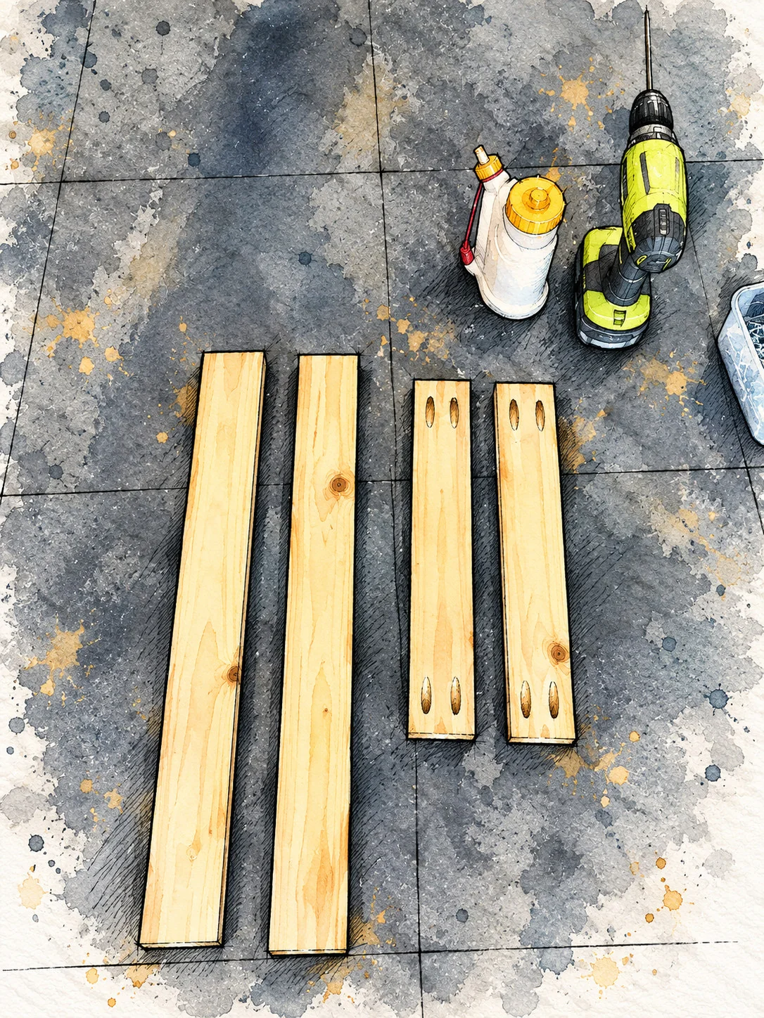
Check the actual opening and chosen hinge clearances before cutting the door parts. Make two L stiles and two M rails for each door. Label the pieces so matched pairs stay together.
Drill the rails
The rails fit between the full-length stiles. Drill pocket holes in both ends on each rail’s back face, using the jig setting for measured stock thickness. Keep the best wood faces outward.
CHECK BEFORE MOVING ON
One door uses four pieces; two doors need eight. Do not confuse 31 3/4 in door stiles with the 32 in face stiles.
WORKSHOP VIEW 13 / FLUSH BUTT JOINT
Join a door corner
Join a door corner · Tin Door Cabinet
Clamp on a flat surface
Place a rail end against the long edge of a stile. Apply glue to the joint and clamp both faces flush. Support the frame so it cannot twist while driving the screws.
Seat the pocket screws
Use 1 1/4 in (31.8 mm) pocket-hole screws through the rail into the stile. Keep the driver aligned with the pocket and stop when the joint closes. Repeat at all four corners.
CHECK BEFORE MOVING ON
The rail ends butt into the stiles. There are no miters, laps or grooves to cut.
ASSEMBLY 09 / MAKE TWO MATCHING DOORS
Check the door frames
Check the door frames · Tin Door Cabinet
Keep the rectangles square
Before the glue sets, compare both diagonals of each door. The standard frame is 17 1/16 in (433.4 mm) wide and 31 3/4 in (806.5 mm) high.
Test them in the opening
Use temporary spacers to hold both frames at the intended reveal. Check hinge swing, meeting gaps and top/bottom clearance. Correct the fit before adding backing or finish; do not force the doors into place.
CHECK BEFORE MOVING ON
The door frames must sit flat, close freely and leave the clearances required by the selected hinges.
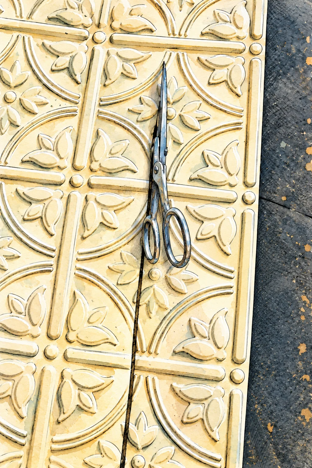
WORKSHOP VIEW 15 / DECORATIVE INSERTS
Cut the faux tin
Cut the faux tin · Tin Door Cabinet
Match the pattern
Lay out the two thin faux-tin pieces so the embossed design aligns attractively across the doors. Use the actual backers and visible openings to mark the cut lines.
Cut without damaging the relief
Use scissors or shears approved for the chosen material. Support the sheet, keep your free hand away from the blades and smooth any sharp cut edges. The faux tin is decorative; the plywood carries it.
CHECK BEFORE MOVING ON
Dry-fit each insert. It must cover the visible opening without interfering with the door frame or hardware.
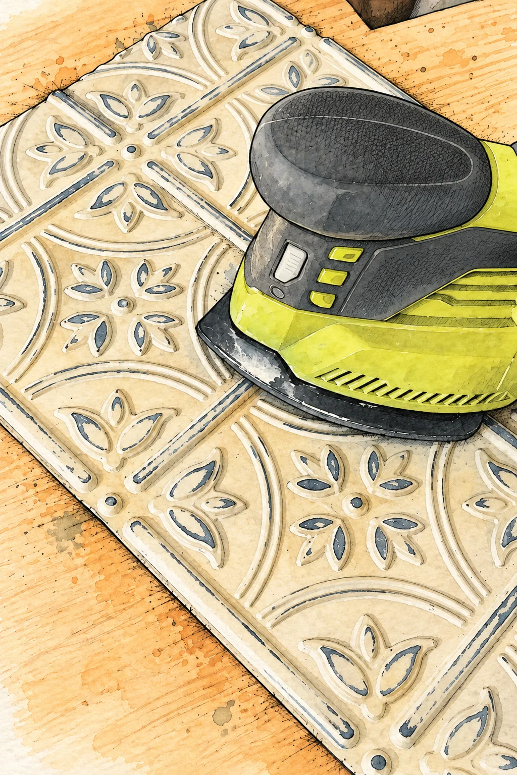
WORKSHOP VIEW 16 / OPTIONAL DISTRESSED FINISH
Prepare the panel finish
Prepare the panel finish · Tin Door Cabinet
Finish before assembly
Paint the faux tin with a coating compatible with its material. Paint or stain the door frames separately. Let each finish dry as directed before gluing the pieces together.
Distress only if suitable
The view shows light sanding of raised details for a worn effect. Test an offcut first and follow the panel and paint instructions. Use very light pressure or hand sanding; do not grind through thin material.
CHECK BEFORE MOVING ON
Distressing is optional. Remove dust and let the finish cure sufficiently for the chosen adhesive.
ASSEMBLY 10 / BACKER AND FAUX TIN
Secure the door inserts
Secure the door inserts · Tin Door Cabinet
Bond the decorative layer
Hot-glue the dry faux-tin sheet to the outward-facing side of plywood backer G. Use glue compatible with the selected sheet and finish. Keep fingers clear of hot adhesive and allow it to set.
Fasten the plywood mechanically
From the rear, center the covered backer over the door opening, with the decorative face showing through the front. Staple or brad-nail the plywood to the door frame. Check fastener length on scraps to avoid face breakthrough.
CHECK BEFORE MOVING ON
This rear view shows plain plywood. Hot glue holds the faux tin; staples or nails retain the plywood backer.
FINISH / HANG AND ADJUST
Hinges pulls and final fit
Mount the doors
Support each door on spacers at the selected reveal. Position two surface hinges along each outer edge according to their instructions. Mark pilot holes, drill to a controlled depth and use the manufacturer’s compatible screws.
Test the full swing
Open and close both doors repeatedly. Confirm that the hinge leaves, backers and decorative panels do not collide with the face frame or center facing. Adjust the fit before tightening the final screws. Do not hide binding by forcing a door shut.
Install the pulls
Use one pull on each door near the meeting edges. Lay out both locations together so they match. Follow the pull’s hole spacing and use bolts or screws sized to the actual frame thickness; keep drill breakout off the visible face.
Finish the cabinet
Fill exposed nail holes if desired, smooth edges and remove dust. Apply the chosen compatible interior finish according to its label. Protect the top as appropriate for its use, and allow full cure before placing items on it.
Install the anti-tip restraint
Move the cabinet into place with help and make it stable and level. Secure it to suitable wall structure using a cabinet restraint and fixings appropriate for that wall. Do not rely on thin paneling or the cabinet back alone.
FINAL CHECK / READY FOR USE
Inspect and care for the cabinet
Structure
• Cabinet sits firmly without rocking or racking. • Shelves, top, face frame and base wraps are secure. • All pocket screws are seated; no wood is split. • Back is flat and fixed to sound cabinet edges.
Doors and inserts
• Both doors swing and close freely with even gaps. • Four hinges and two pulls are tight. • Faux tin is bonded to its plywood backing. • Both backers are mechanically fixed to the frames. • No staple, nail or screw point is exposed.
Use safely
No tested load capacity is specified. Store heavier items low and distribute weight rather than concentrating it on one shelf. Never climb, stand or sit on the cabinet. Keep children from hanging on open doors.
Care
Wipe up moisture promptly. Clean with products suitable for the finish and decorative panels. Lift rather than drag when moving. Recheck the wall restraint, hinges, fasteners and door alignment periodically.
Keep the fit record
Write down the selected hinge model, actual door gaps and finish products for future adjustment or repair. Retain the remaining offcuts for finish tests and hardware trials.
 FREE WOODWORKING PLAN