Yes. The complete plan is available to read on this page.
THE FREE BUILD GUIDE
Round Coffee Table
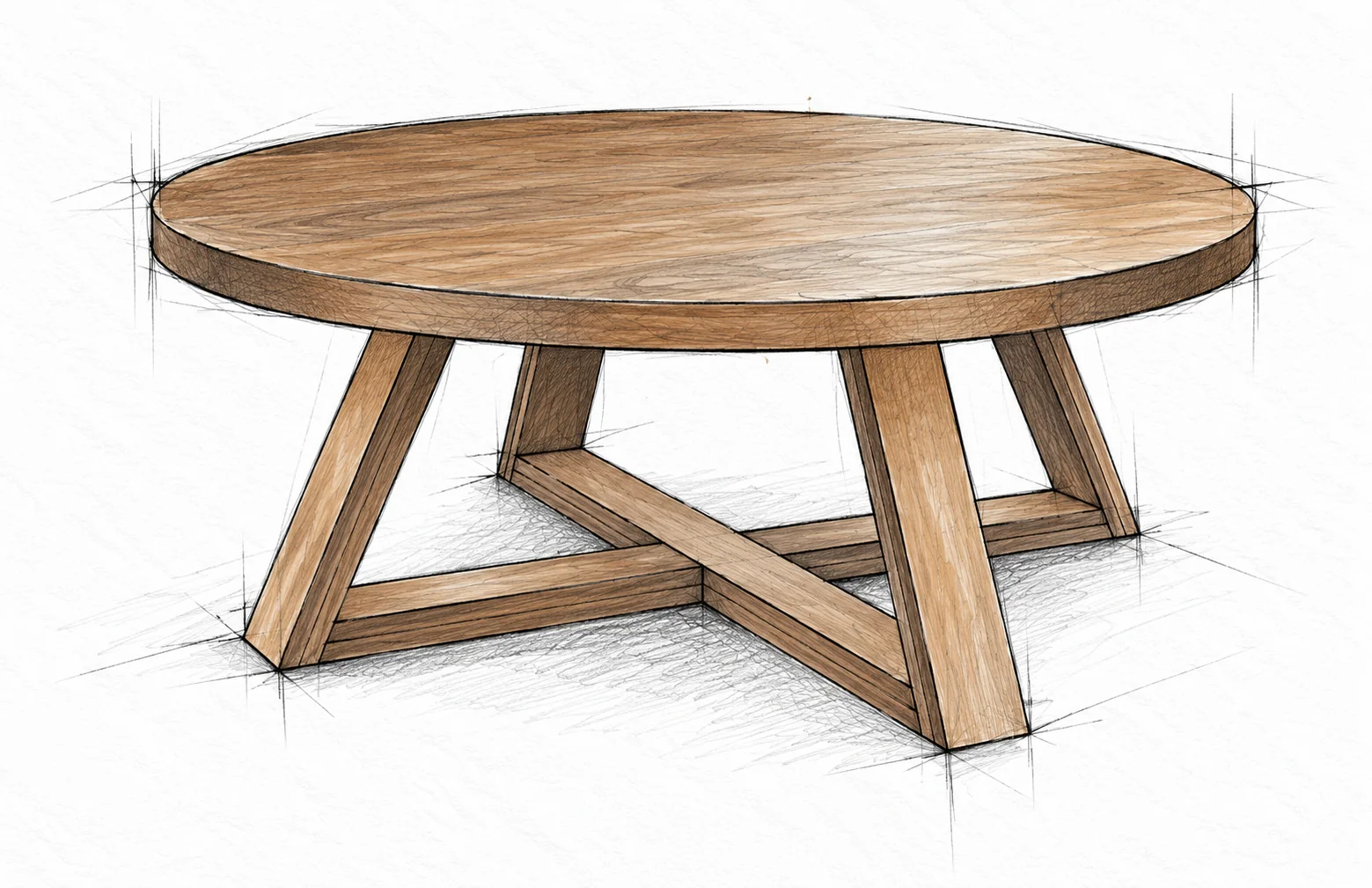
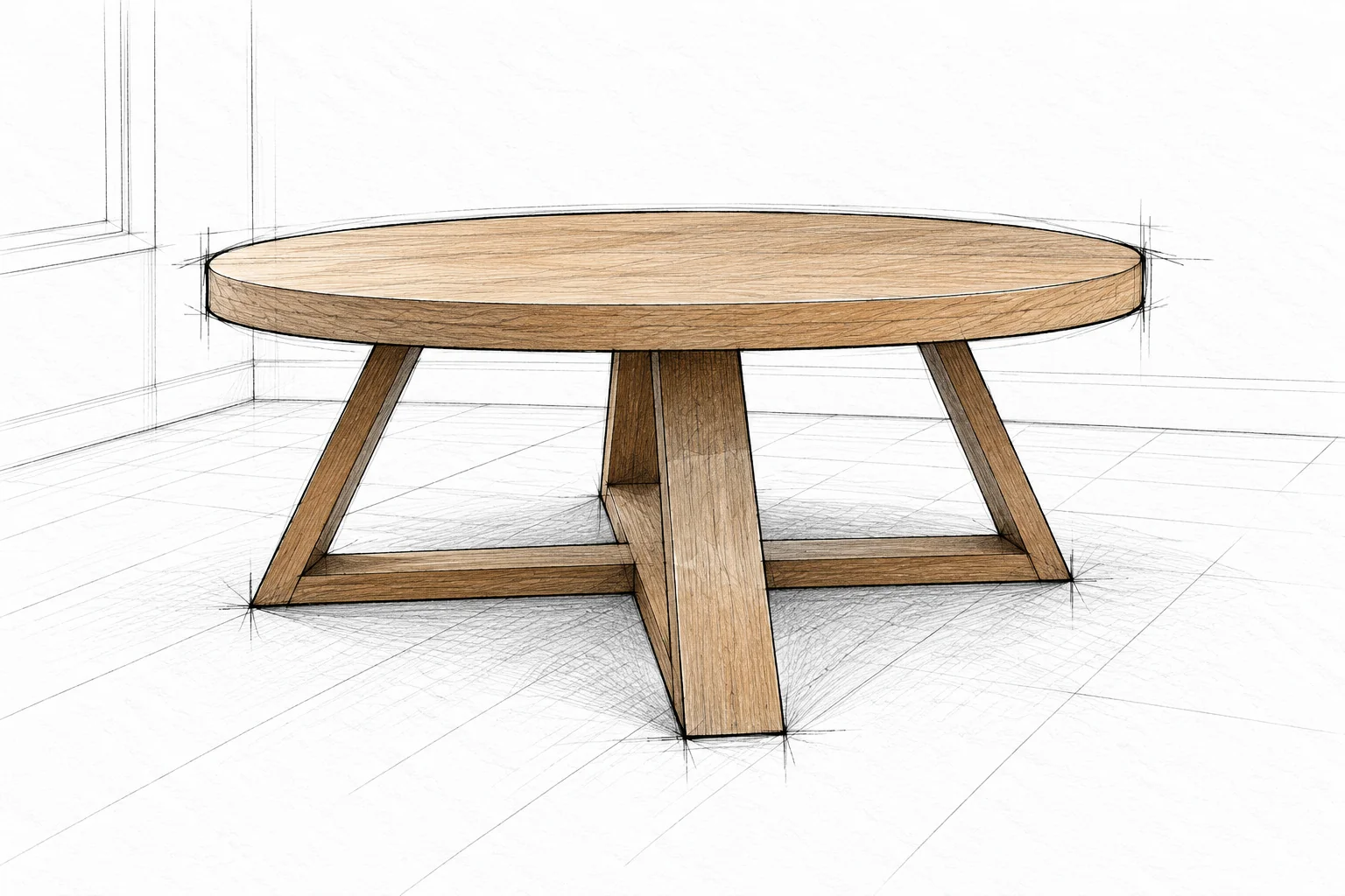
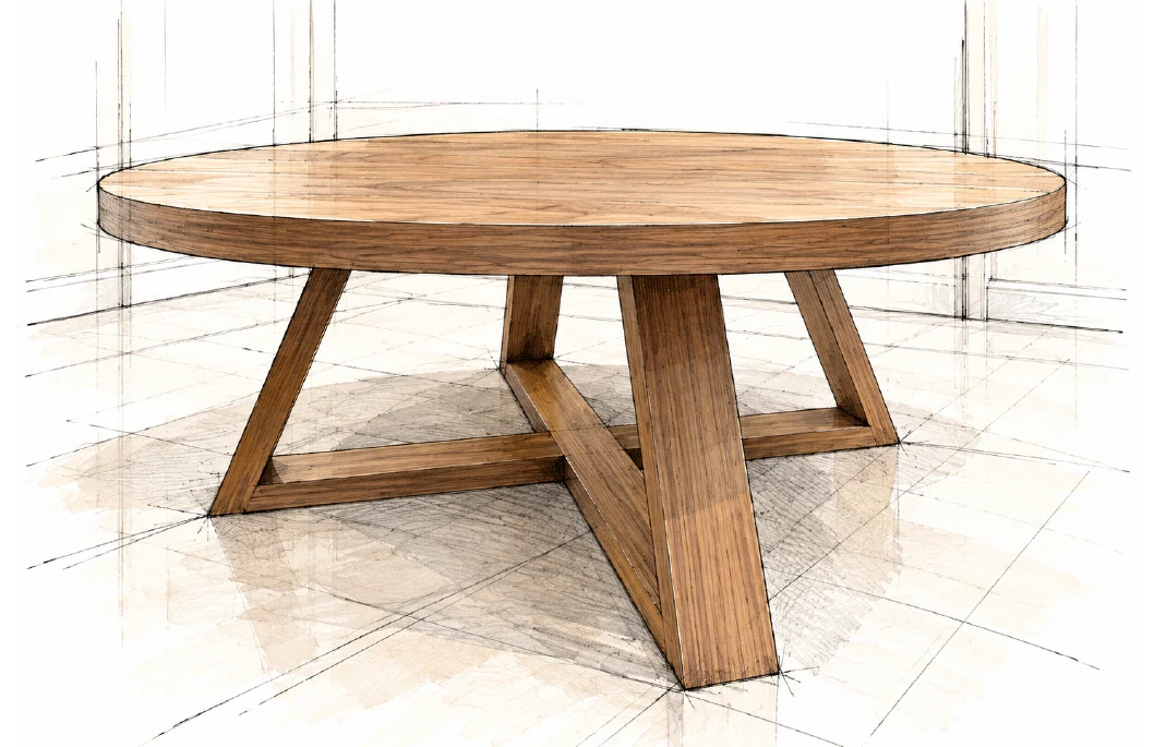
A round plywood coffee table with a thickened rim, splayed legs, and a crossed base.
READ BEFORE CUTTING
Plan the complete build
What you will make
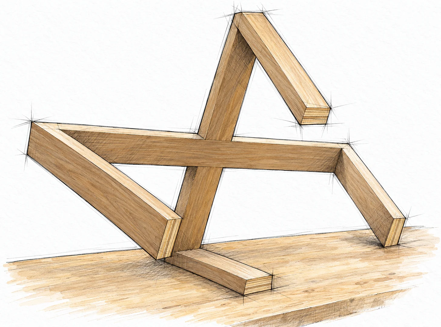
A single plywood disk forms the top. Short plywood blocks thicken only its outer underside, so the top looks thicker without a second full disk. Four laminated legs join a large lower cross and a smaller upper cross.
Skill and sequence
This is an intermediate project explained step by step. Practise the circle-router setup, edge banding and angled pocket joints on offcuts first. Cut and thicken the top, laminate the base parts, dry-fit the frame, finish the separate pieces, then attach the top.
Use plywood throughout
Use flat, sound, furniture-grade 3/4 in plywood with attractive veneer. Do not replace the disk with solid boards using this attachment method. The plywood construction avoids the cross-grain movement problem of a solid-wood top.
Measure the actual material
Nominal 3/4 in is 19.1 mm, but actual sheet thickness varies. Match all parts to one thickness, measure it, and test the pocket-jig settings and screw exit paths on identical scraps. Do not scale the table or substitute thinner sheet without redesign.
STOCK FOR ONE PROJECT
Materials and fasteners
Buy the full sheet before laying out the parts. Keep the two pocket-screw lengths separate from ordinary wood screws. Extra stock for practice is useful.
Quantity
Item
Size or specification
1 sheet
Veneered plywood
Nominal 3/4 × 48 × 96 in 19.1 × 1219.2 × 2438.4 mm
50 ft
Iron-on veneer edge band
2 in wide × 50 ft 50.8 mm × 15.24 m; match plywood
As needed
Wood glue
Interior woodworking glue suited to plywood; follow its clamp and cure times
1 pack each
Pocket screws
1-1/4 in (31.8 mm) and 2 in (50.8 mm); select a type suitable for your plywood and jig
1 pack
Wood screws
1-1/4 in (31.8 mm); for the lower lap and top attachment
Optional
Pin or brad nails
1-1/4 in (31.8 mm), compatible with the selected nailer; temporary glue-up holding only
As needed
Finish and abrasives
Furniture wax, clean cloths, sanding supplies and dust removal materials
STOCK FOR ONE PROJECT / CONTINUED
Materials and fasteners
Quantity
Item
Size or specification
Optional set
Furniture feet
Choose for actual base thickness and floor; verify screw depth before fitting
Offcuts
Jig and protection stock
Straight router pivot arm, sacrificial support sheet, spacers and protective cauls
Fastener pack counts depend on the package and chosen optional method. The lower cross has two end pockets per arm; the upper cross has end pockets plus the short-arm centre connections. Never use longer screws as a substitute.
WORKSHOP SETUP
Tools for the operations
Tool
Purpose or requirement
Tape, pencil and square
Mark centres, repeat widths, and check perpendicular crosses.
Track saw or table saw
Break down the sheet and rip consistent 1-1/2 in and 3-1/2 in strips. Use proper support and guides.
Miter saw or suitable bevel setup
Make 7-1/2 degree rim miters and 25 degree base end cuts. Use a safe small-piece fixture.
Plunge router and circle jig
Cut the 46 in circle with a spiral upcut bit in controlled shallow passes.
Bearing-guided pattern or flush-trim bit
Trim the added rim flush with the original disk. Select a bearing position that follows the disk.
Pocket-hole jig and stepped bit
Drill joints for both single-layer and laminated plywood, using measured thickness.
Drill and driver
Pilot, countersink when needed, and drive screws with a long pocket-screw driver bit.
Clamps and flat cauls
Hold laminations and joints without shifting. Pads must oppose each other across the work.
Iron and edge trimmer
Bond veneer banding, then trim the overhang flush; use heat settings recommended for the band.
Sanding tools and dust extraction
Ease edges without sanding through thin veneer; remove dust before finishing.
WORKSHOP SETUP
Work safely at each stage
Protect yourself and support the work
Wear eye and hearing protection and suitable dust protection. Secure the work on a flat support, keep hands away from cutters, and manage cables and hoses. Disconnect power before changing bits or adjusting a jig.
Keep small parts away from the blade
Do not hand-hold short rim blocks beside a miter-saw blade. Use a suitable clamped carrier or stop arrangement that cannot trap the offcut. Follow the saw instructions, let the blade stop, and remove waste only when safe.
Control the router
Use a securely attached pivot arm and a sacrificial surface underneath the plywood. Keep the router base supported and the pivot engaged. Make several passes rather than cutting through the full sheet at once; use the tool maker's feed direction.
Protect hidden fastener paths
Keep optional pins or brads out of the future flush-trim path and away from each other. Never rout into metal. Drill pilot holes with a depth stop so they cannot emerge through a finished face.
Treat finish and hot tools safely
Park the hot iron on a heat-safe surface. Ventilate as the finish label requires; keep ignition sources away from flammable products. Store or dispose of used finishing cloths exactly as the product directs.
CUT AND LABEL BEFORE ASSEMBLY
Cut list
All stock comes from the plywood sheet. Dimensions are inches first, with millimetres rounded to 0.1 mm. Rough blanks are trimmed later; do not treat them as finished member lengths.
Part
Qty
Stock and use
Cut in
Cut mm
A
1
3/4 in plywood Top disk
46 diameter
1168.4 diameter
B
24
3/4 in plywood Rim blocks
1-1/2 wide × 5-7/8 nominal rough
38.1 wide × 149.2 nominal rough
C
8
3/4 in plywood Leg layers
3-1/2 × 19-3/4 rough
88.9 × 501.7 rough
D
2
3/4 in plywood Continuous lower-rail layers
3-1/2 × 42 rough
88.9 × 1066.8 rough
E
4
3/4 in plywood Lower-rail overlay blocks
3-1/2 × 19-1/4
88.9 × 489.0
F
1
3/4 in plywood Long upper-cross rail
3-1/2 × 22-1/4
88.9 × 565.2
G
2
3/4 in plywood Short upper-cross arms
3-1/2 × 9-3/8
88.9 × 238.1
CUT AND LABEL BEFORE ASSEMBLY / CONTINUED
Cut list
Keep the blank groups separate
The eight longer C blanks make four legs. The four E blocks are for the lower half-lap rails, not the legs. Label the groups before gluing.
Rim blocks must fit the actual disk
The 5-7/8 in value is a nominal rough target, not a verified long-point dimension. Use 7-1/2 degree end miters, make a sample and dry-fit the complete rim to the actual circle before repeating cuts. Do not assume the nominal length alone guarantees a closed ring.
Angle and length convention
Leg end cuts are parallel, 25 degrees from square across the laminated thickness. Measure the 18-1/2 in length along either long side between its end corners, not across opposite farthest tips. Cross-rail outer ends also use 25 degree cuts, oriented to meet the legs; their stated lengths are the longest edges.
CHECK AFTER LAMINATION
Finished geometry
Feature
Inches
Millimetres
Tabletop diameter
46
1168.4
Nominal overall height without feet
17-1/2
444.5
Top field thickness
3/4 nominal
19.1 nominal
Thickened outside rim
1-1/2 nominal
38.1 nominal
Each leg width and laminated thickness
3-1/2 × 1-1/2
88.9 × 38.1
Finished leg side length
18-1/2
469.9
Finished lower-rail longest length
37-1/8
943.0
Lower half-lap opening
3-1/2; fit to rail width
88.9; fit to rail width
Upper cross overall longest span
22-1/4
565.2
OVERALL REFERENCE
Understand the table
46 in diameter / 17-1/2 in nominal height
Understand the table · Round Coffee Table
Look at the load path
The top bears on the small upper cross. Four sloping legs carry it down to the wide lower cross. The top overhangs the base, while the larger lower cross spreads the footprint.
Allow for the real build
Actual plywood thickness, edge band and optional feet can change the final outside size slightly. Check the assembled base before fastening the top. This is a coffee table, not a seat, step or climbing surface.
CUTTING LAYOUT
Lay out the sheet
One 3/4 × 48 × 96 in plywood sheet
Lay out the sheet · Round Coffee Table
Reserve the large pieces first
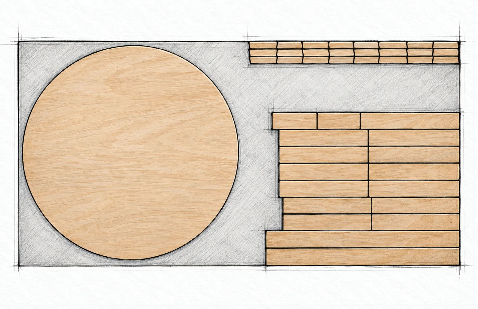
Lay out the 46 in circle at one end. Reserve two 42 in lower-rail blanks in the remaining area before cutting small pieces. Plan three strips at 1-1/2 in wide for the rim and nine strips at 3-1/2 in wide for the base.
Include every saw cut
The wide-strip group contains one upper-cross row, four two-blank leg rows, two two-block overlay rows and two uncut lower-rail rows. Mark actual kerf between pieces. Keep the rim strips as long as the available offcut allows until the sample rim fit is proven.
STEP 01 / CIRCLE ROUTING
Cut the circular top
A / Plunge router / Pivot arm / Sacrificial support
Cut the circular top · Round Coffee Table
Set the cutting radius
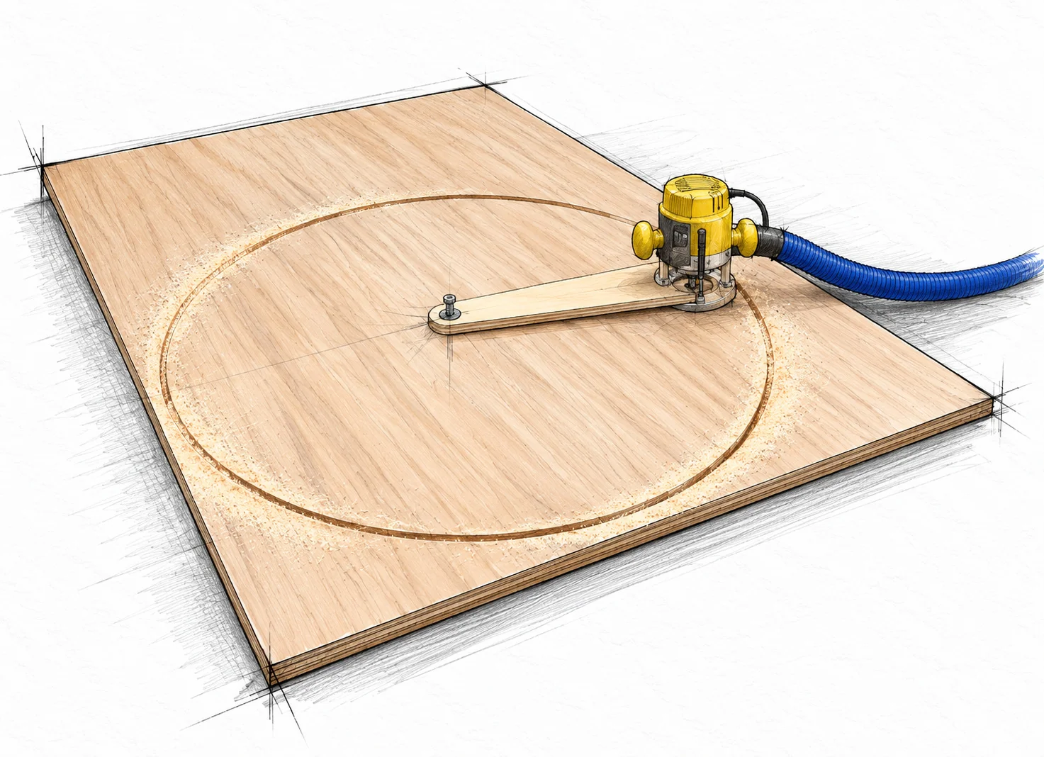
Locate the centre on the underside. Attach a straight scrap arm to the router and set the pivot so the cutting edge that forms the finished disk is 23 in (584.2 mm) from the pivot centre. The cutter centre is not the same reference as its cutting edge.
Make controlled passes
The pivot screw must hold securely without piercing the show face. The indicated screw length is 1-1/4 in (31.8 mm), but check its projection through your arm first. Support the disk and surrounding waste, rout shallow passes, then check the circle before removing the jig.
STEP 02 / RIM LAYOUT
Thicken the outside edge
A + B × 24 / Wood glue / Optional 1-1/4 in pins or brads
Thicken the outside edge · Round Coffee Table
Fit before fixing
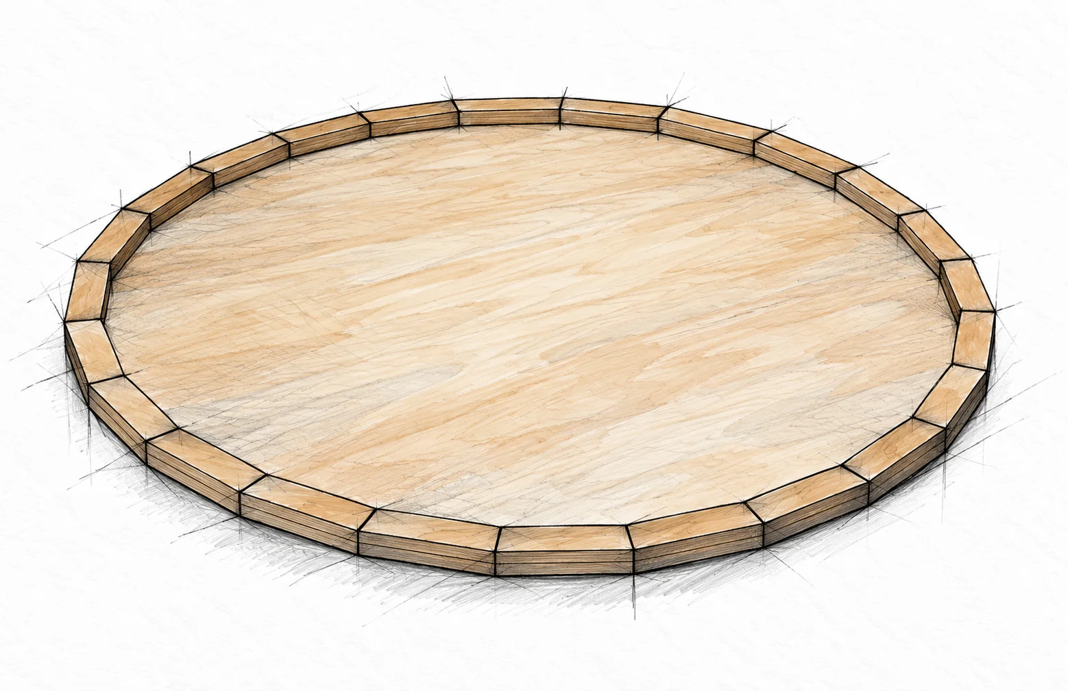
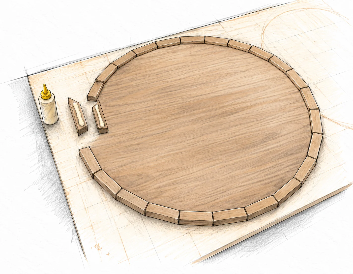
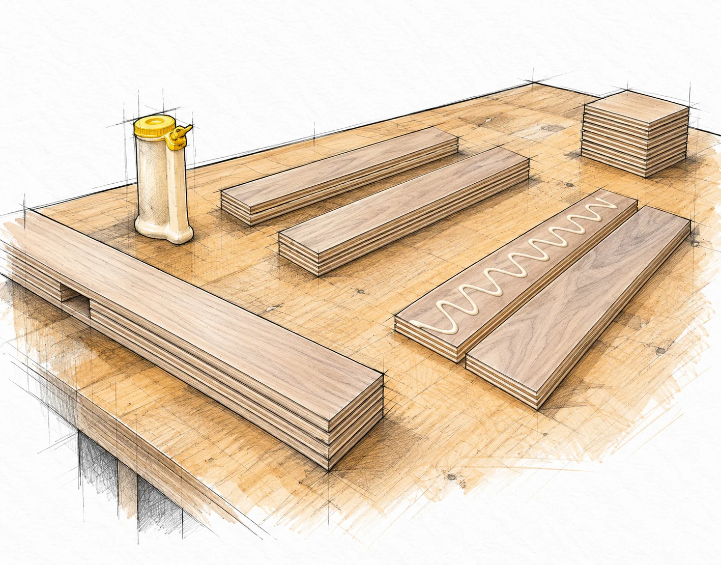
Place the disk show-face down. Arrange the 24 short rim blocks around its underside. At each block, the middle of the outside edge must be flush with or slightly outside the disk; the corners overhang for trimming. Do not put the middle inside the circle.
Confirm the full ring
Test-fit all blocks before glue, checking the joints and complete support along the edge to be banded. Use the actual circle, not an assumed miter-length datum, to prove the layout. If it does not fit, stop and recheck the sample and measurements before cutting the remaining strips.
STEP 02 / RIM GLUE UP
Glue the rim blocks
Wood glue / Clamps or optional temporary pins or brads
Glue the rim blocks · Round Coffee Table
Bond the broad faces
Spread a thin, even glue layer over each block underside and place it back in the dry-fitted position. Keep the planned overhang. Clamp with cauls, or use compatible 1-1/4 in (31.8 mm) pins or brads only to hold the glued layers while curing.
Keep the cutter path clear
Check nail length against the actual two-layer thickness and aim away from the show face. Place any metal fasteners well inside the material that will remain. Mark their positions and keep the outer flush-trim path entirely metal-free.
STEP 02 / RIM FLUSH TRIMMING
Trim the rim flush
Cured rim / Bearing-guided router bit
Trim the rim flush · Round Coffee Table
Let the disk guide the cutter
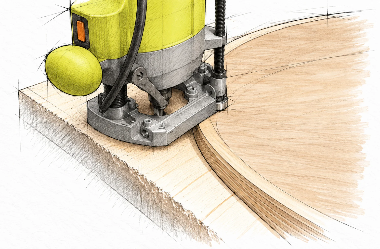
After the glue cures, use the already-round disk edge as the bearing reference. Choose a bit with its bearing at the correct height to follow that original disk while its cutting edges remove only the added blocks' overhang.
Keep the router stable
Support the router base so it cannot tip off the narrow rim; provide a broad, secure support at the same level where needed. Work in controlled passes and inspect the complete circumference. Do not sand or cut into the disk to hide an undersized block.
STEP 02 / TOP EDGE BANDING
Cover the circular edge
2 in (50.8 mm) iron-on veneer banding
Cover the circular edge · Round Coffee Table
Bond around the curve
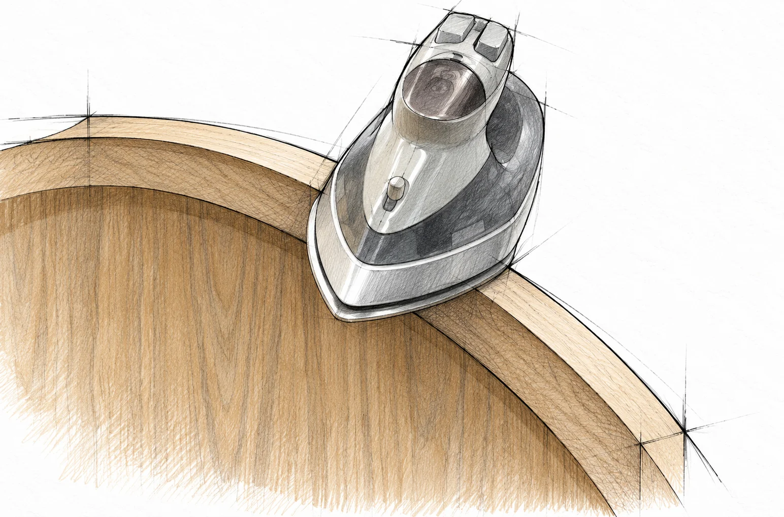
Remove dust. Centre the wide banding on the thickened outside edge with a little overhang on each side. Follow the adhesive maker's heat and pressure directions and work around the curve, keeping the iron sole on the edge, not the veneer face.
Trim after cooling
Press the heated band firmly into place, let it cool, then trim its two margins flush with the faces. Work with the veneer grain to avoid tearing it. Lightly ease the sharp edge without cutting through the thin band or face veneer.
STEP 03 / LEG GEOMETRY
Make four matching legs
C × 8 / Four two-layer legs
Make four matching legs · Round Coffee Table
Laminate the longer blanks
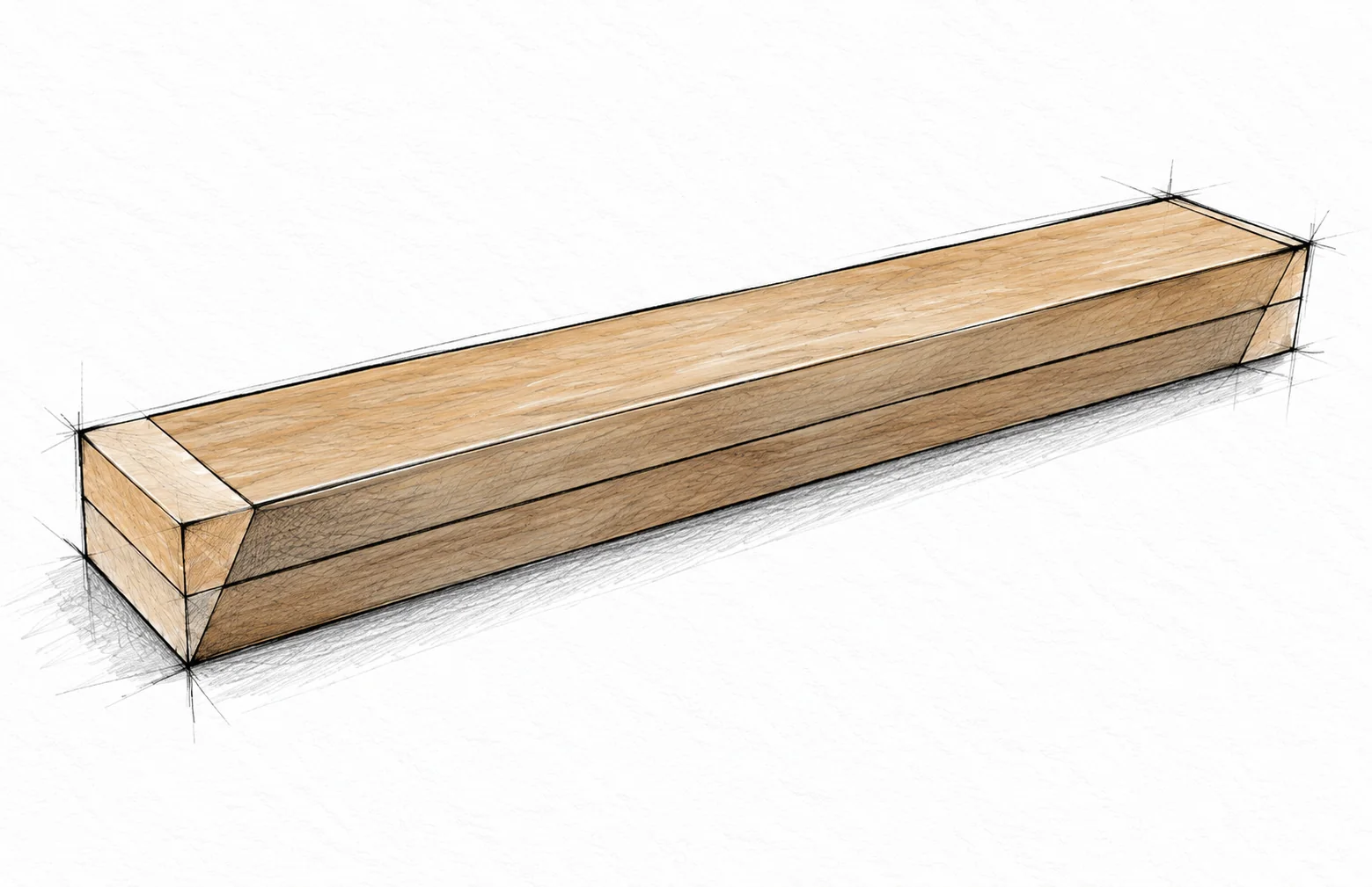
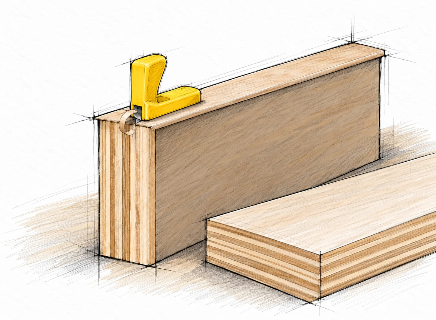
Glue pairs of the 19-3/4 in (501.7 mm) rough leg blanks face to face. Align their long edges, clamp them flat, and let the adhesive cure. Band the exposed long edges, then trim and ease the banding.
Cut the finished length
Make parallel 25 degree end bevels across the laminated thickness. Finish each leg at 18-1/2 in (469.9 mm) along either long side. The extra blank length is trimming allowance. Compare all four legs side by side before moving on.
STEP 03 / LEG LAMINATION CLOSE VIEW
Keep laminations flat
Four matched plywood pairs / Glue / Flat cauls
Keep laminations flat · Round Coffee Table
Spread the glue evenly
The two broad plywood faces form the joint; a decorative edge strip cannot replace this bond. Spread glue over the mating face, pair the blanks, and align them before tightening clamps.
Check both faces
Use opposing clamp pads and protective cauls to keep each pair flat, rather than bowing it. Wipe away squeeze-out while appropriate for the glue. Optional pins can stop sliding but are not a substitute for the glue bond or its cure time.
STEP 03 / LEG EDGE FINISHING
Trim the leg banding
Cured laminated leg / Veneer band / Edge trimmer
Trim the leg banding · Round Coffee Table
Keep the cutting edge at the margin
Support the leg securely with the banded edge accessible. Let the band cool first. Guide the edge trimmer against the adjacent wood face so its blade removes only the thin overhang. Trim the ends and long margins separately, keeping the blade flush with the wood rather than cutting into veneer.
Work with the grain
Take light passes and reverse approach if the band begins to split ahead of the blade. Finish with a light sanding block. Keep the finished edge flush before the final 25 degree cuts so all legs can seat cleanly against the rails.
STEP 04 / LOWER HALF LAP CONSTRUCTION
Build the lower rail laps
D × 2 + E × 4 / Wood glue
Build the lower rail laps · Round Coffee Table
Create the notch by layering
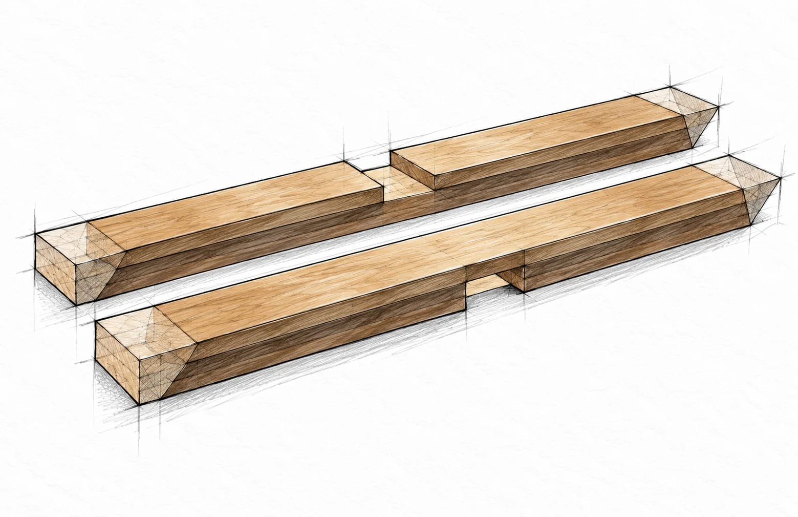
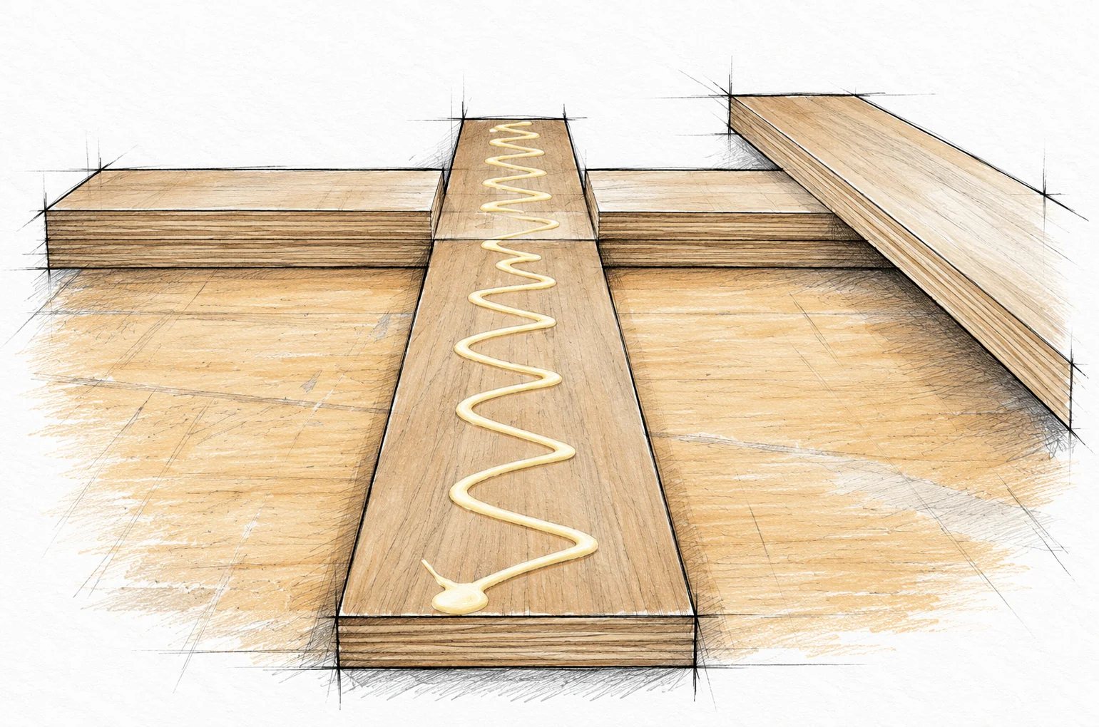
For each lower rail, glue two 19-1/4 in (489.0 mm) overlay blocks onto one 42 in (1066.8 mm) continuous strip. Flush the outside ends and leave the centred 3-1/2 in (88.9 mm) gap between the blocks. Use an actual mating rail-width offcut as a snug spacer; do not glue it in.
Leave the joint faces bare
One finished rail turns over so its notch faces down into the other rail's upward notch. Do not edge-band the mating lap surfaces or the edge portions within the joint: extra veneer there prevents the cross from fitting. Band only the exposed edges.
STEP 04 / LOWER RAIL LAMINATION CLOSE VIEW
Glue without closing the gap
Two lower-rail laminations / Removable width spacer
Glue without closing the gap · Round Coffee Table
Keep the gap centred
Dry-fit each overlay pair before gluing. The two equal blocks and the central gap total the continuous strip length. Spread glue on the intended bond areas, keep the spacer clean, and hold all layers flush and flat while curing.
Trim the two rails alike
After curing and edge treatment, make the outer 25 degree cuts shown by the joint geometry. Finish both lower rails at 37-1/8 in (943.0 mm) on the longest edge, keeping the lap centred. Test the two notches together before drilling.
STEP 05 / LOWER CROSS ASSEMBLY
Join the lower cross
Two finished lower rails / 1-1/4 in ordinary wood screws
Join the lower cross · Round Coffee Table
Drill the end pockets first
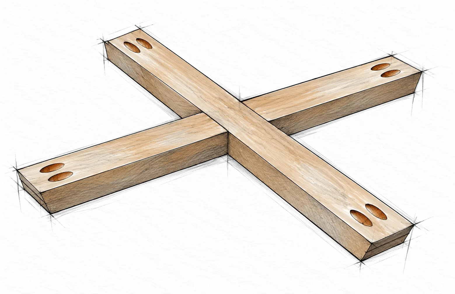
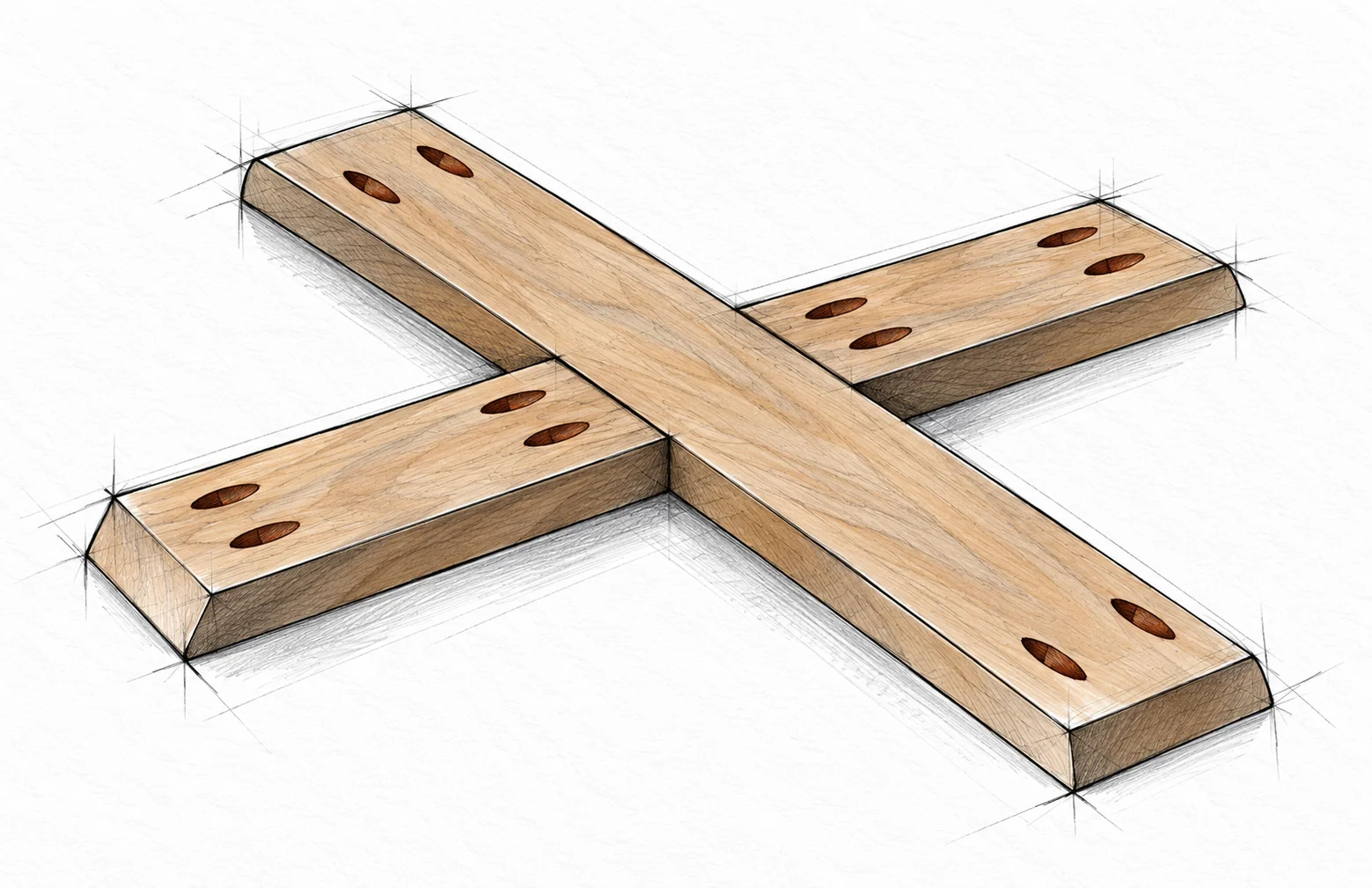
On the underside, drill two pocket holes near each outer end using the jig setting for the actual laminated thickness. These pockets will later receive 2 in (50.8 mm) pocket screws into the legs; do not confuse them with the centre fasteners.
Close the half lap
Glue the mating lap faces, press the rails together at right angles and check that both outer faces are flush. Secure the centre from underneath with 1-1/4 in (31.8 mm) wood screws or compatible brads. Pilot first and check that no tip can break through.
STEP 05 / POCKET DRILLING CLOSE VIEW
Set the pocket jig correctly
Pocket-hole jig / Stepped bit / Laminated lower rail
Set the pocket jig correctly · Round Coffee Table
Use the measured thickness
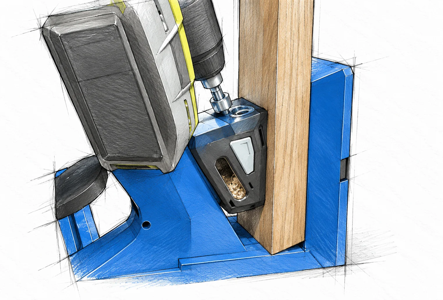
Set the guide block and drill-stop collar for the actual laminated rail, following the jig instructions. Clamp the wood firmly against the fence with the pressure pad opposed by the fence. The bit must enter the metal guide sleeve, not the clamp pad.
Test the screw path
Drill a matching scrap joint first. Confirm the pocket and 2 in (50.8 mm) screw reach the leg without emerging through its outer face. Repeat the end-pocket positions consistently on the four lower-cross arms; keep the joint faces free of chips.
STEP 06 / UPPER CROSS CONSTRUCTION
Assemble the upper cross
F × 1 + G × 2 / 1-1/4 in pocket screws
Assemble the upper cross · Round Coffee Table
Keep this cross one layer thick
The 22-1/4 in (565.2 mm) rail runs through the centre. The two 9-3/8 in (238.1 mm) arms butt against its opposite sides, at the midpoint, to form a perpendicular cross. This is not a second laminated half lap.
Bevel and join
Keep the inner ends of the short arms square. Cut 25 degree bevels only on the four outside ends, preserving the specified longest lengths. Drill the centre-connection and outer-end pockets for actual single-layer thickness. Assemble the centre with 1-1/4 in (31.8 mm) pocket screws and check it flat and square.
STEP 07 / BASE ASSEMBLY REFERENCE
Connect the four legs
Upper cross / Lower cross / Four legs
Connect the four legs · Round Coffee Table
Work upside down
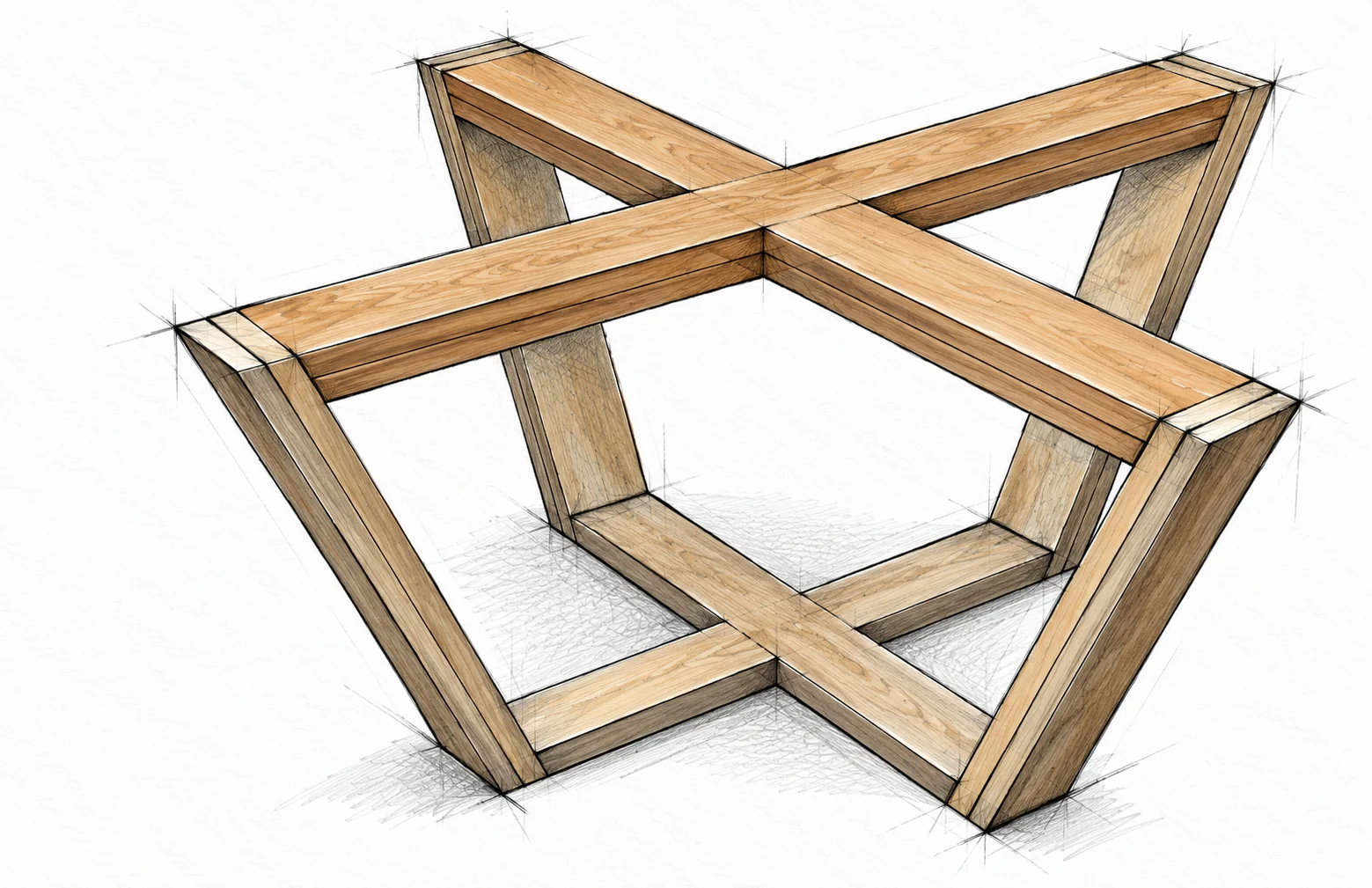
Place the smaller upper cross on a flat protected surface. Position the four legs so the base widens toward the larger lower cross above. Dry-fit all bevelled contacts; every leg end should sit flush, without twisting the crosses out of plane.
Choose the screw by joint
Fasten the single-layer upper-cross ends to the legs with 1-1/4 in (31.8 mm) pocket screws. Fasten the laminated lower-cross ends with 2 in (50.8 mm) pocket screws. Do not use 2-1/2 in (63.5 mm) screws: they can pierce the legs.
STEP 07 / BASE ASSEMBLY CLOSE VIEW
Align before tightening
Base frame / Long driver bit / Protective supports
Align before tightening · Round Coffee Table
Bring the joints together
Support the frame securely as you turn it to reach the pockets. Clamp each joint with opposing pressure across its mating faces, then drive the correct screw until snug. Do not use screw force to drag an open bevel into alignment.
Check the base on a flat surface
After all four legs are fitted, turn the base upright. All lower contact areas should sit evenly and the upper cross should be level. Check the crosses remain perpendicular and the frame does not rack. Correct any poor fit before finishing.
STEP 08 / FINISHING SETUP
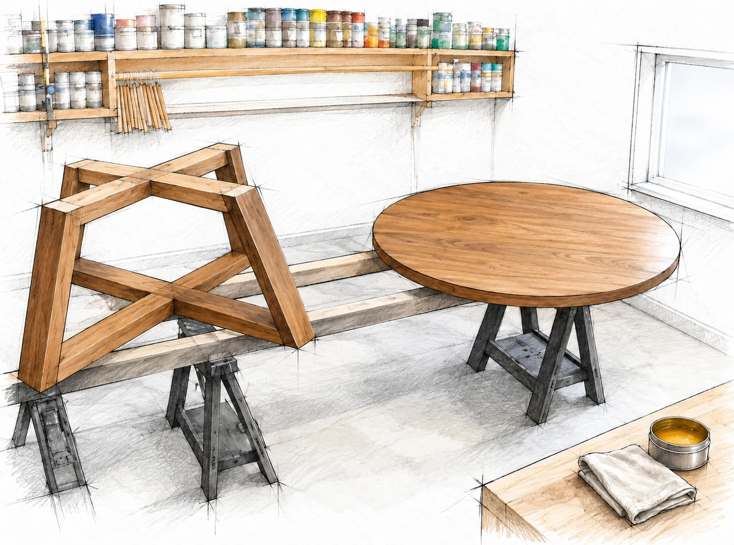
Finish the separate pieces
Completed base / Detached top / Furniture wax
Finish the separate pieces · Round Coffee Table
Prepare the surfaces
Remove glue residue, ease sharp corners and sand gently with the grain without exposing the plywood core. Keep the top and base separate so their undersides and inner faces remain accessible. Vacuum and wipe away dust as required by the finish.
Apply a light wax finish
Use furniture wax suitable for the veneer and follow its application, buffing and curing instructions. Test on an offcut first. Wax gives a natural appearance but is not a spill-proof coating; use coasters and wipe spills promptly.
STEP 09 / TOP ATTACHMENT REFERENCE
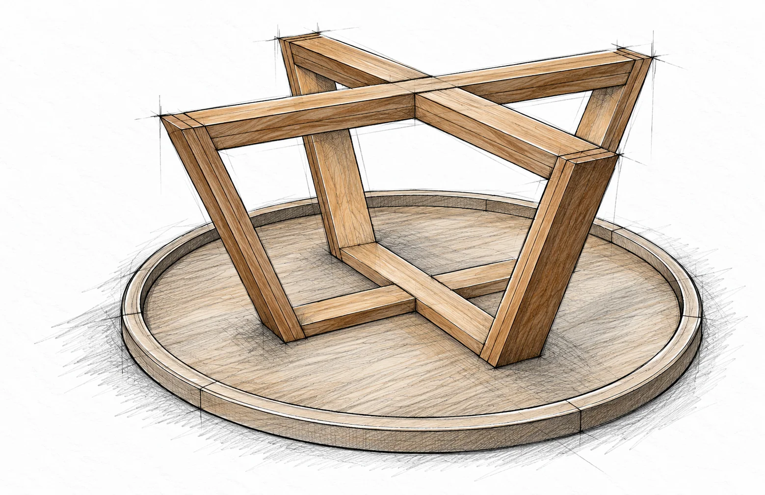
Centre the base under the top
Finished parts / 1-1/4 in ordinary wood screws
Centre the base under the top · Round Coffee Table
Protect the show face
After the finish has cured, set the top upside down on a clean soft surface. Place the inverted base on it with the smaller upper cross touching the underside. Find the disk centre and align the cross centre; compare overhangs in opposite directions.
Plan safe screw locations
Mark attachment holes through the upper-cross arms where they bear fully on the 3/4 in (19.1 mm nominal) disk. Keep clear of pocket holes and their screws. The thickened rim is outside this attachment area and must not be mistaken for the top thickness here.
STEP 09 / TOP FASTENING CLOSE VIEW
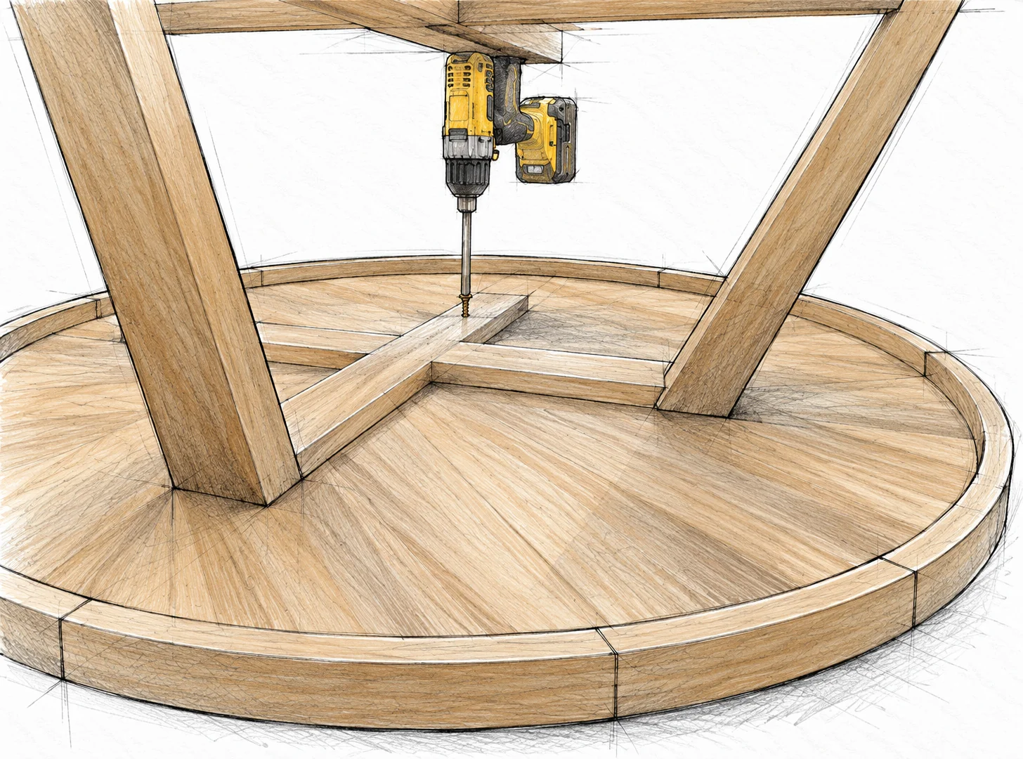
Fasten without piercing the top
1-1/4 in (31.8 mm) wood screws / Pilot bit / Driver
Fasten without piercing the top · Round Coffee Table
Check the complete depth stack
Pilot through the upper-cross rail into the disk with a depth stop. At nominal thickness, a 1-1/4 in screw passing through a 3/4 in rail enters the 3/4 in disk by about 1/2 in (12.7 mm). Verify actual screw projection; deep countersinks reduce the remaining face clearance.
Drive only until snug
Hold the base centred, then drive the screws straight through the rail into the top. Use low torque near the end and do not bury the heads excessively. Optional feet must also have safe screw depth. With help, lift and turn the finished table rather than dragging it.
COMPLETED PROJECT REFERENCE
Check the finished table
Indoor coffee table / Bare top / Level floor
Check the finished table · Round Coffee Table
Inspect before everyday use
Check for wobble, loose joints, proud screw tips, sharp edges and loose veneer. The upper cross must sit firmly against the top. If the table rocks, establish whether the floor or base is uneven before altering any component.
Use and care
Keep the table indoors and dry. Lift it by supported structural members with help, not by pulling the overhanging edge. Use coasters, avoid concentrated loads at the rim, and recheck fasteners and banding periodically. No load rating is claimed.
FINISH AND INSPECT
Complete the final checks
Final checklist
Confirm the four legs match, the lower half lap is flush, the upper cross is flat, and all screw lengths match their joints. Nothing should protrude into the show face or through a leg. Verify that every glued joint has cured and all finishing products are ready for use.
If a joint does not fit
Stop rather than forcing it together. Check the part label, long-point measurement, bevel direction, actual plywood thickness and any unwanted banding within the lap. A gap caused by an incorrect cut is not repaired by a longer screw.
Keep the dimensions intact
Do not enlarge this into a dining table or use it as seating. A larger top, taller legs, different material or changed base footprint affects the structure and needs a new design. Keep your measured cut notes and finish information for later care.
 FREE WOODWORKING PLAN