Yes. The complete plan is available to read on this page.
THE FREE BUILD GUIDE
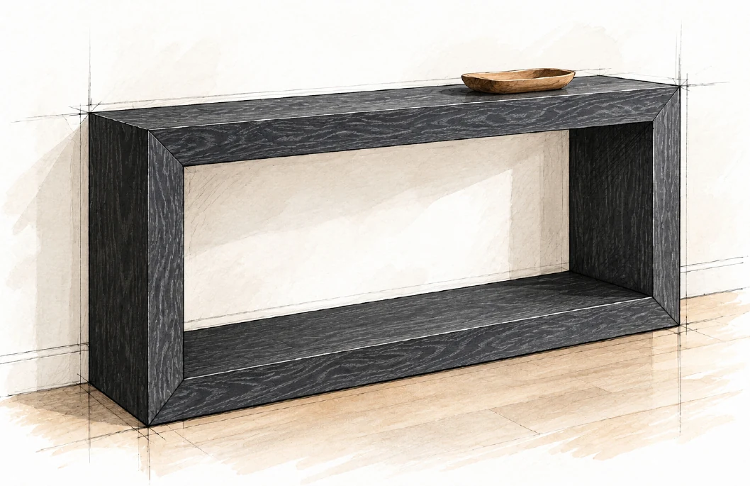
Hollow Panel Waterfall Console
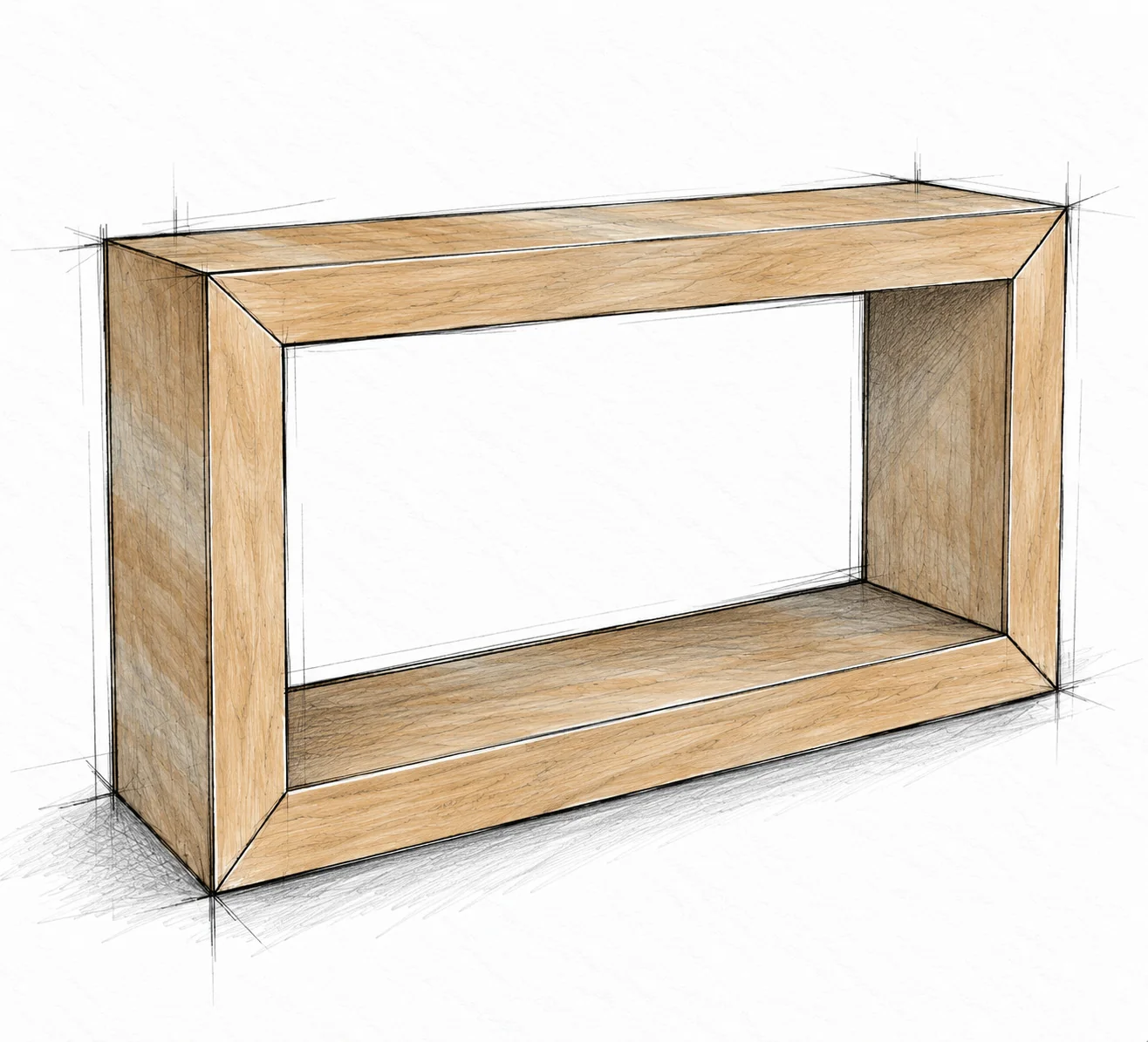
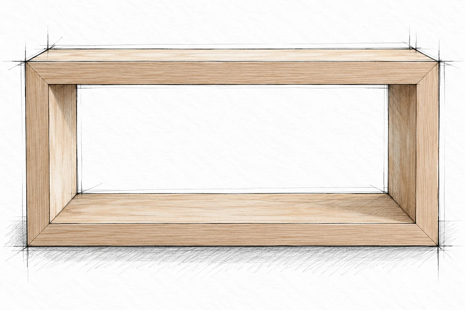
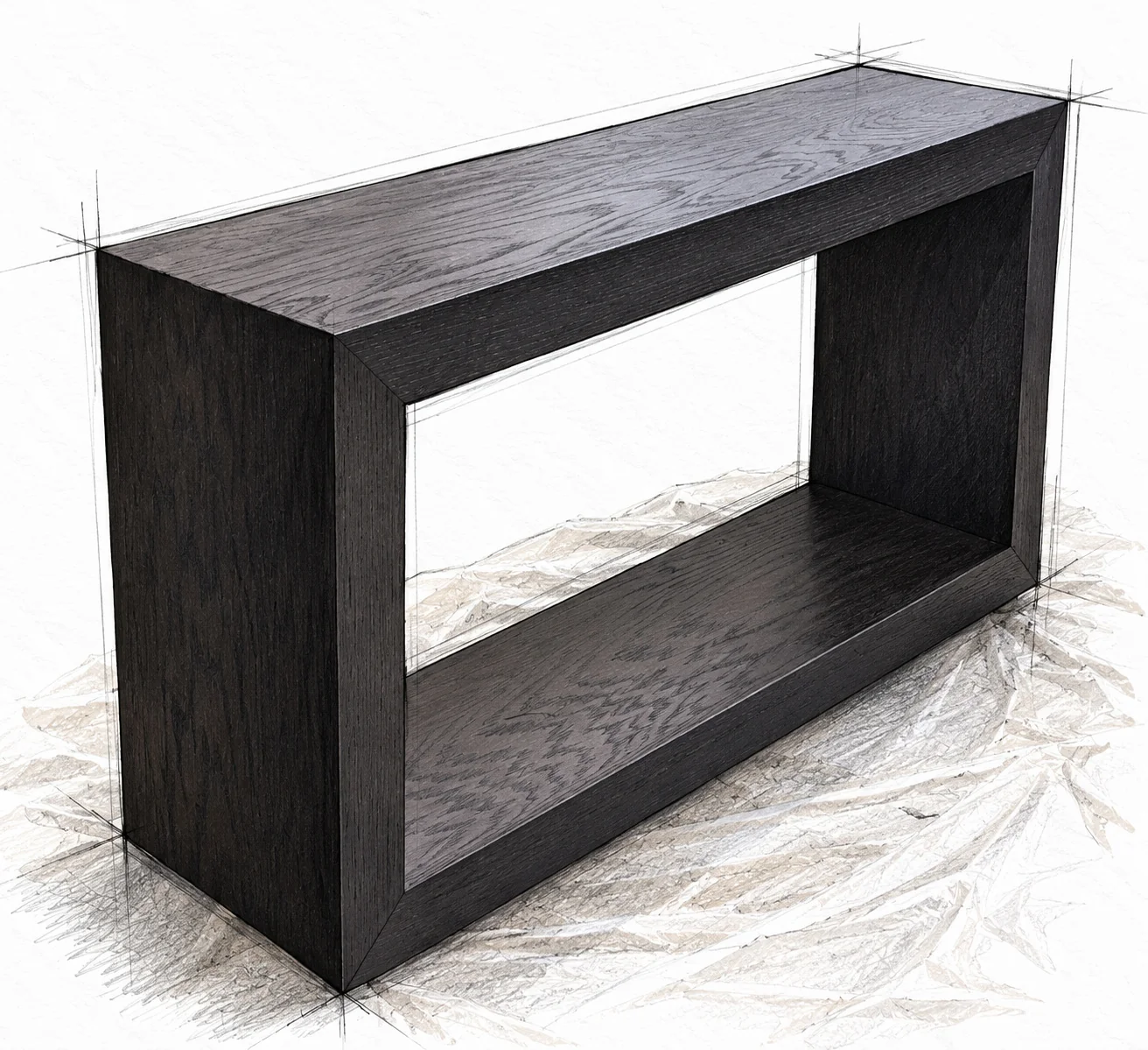
Hollow plywood sides, a low shelf, and crisp mitered oak trim give this console its substantial look.
PROJECT OVERVIEW
Understand the hollow build
Overall 60 W x 13 1/4 D x 30 H in / Indoor display furniture
Understand the hollow build · Hollow Panel Waterfall Console
A thick frame without solid slabs
Plywood skins and short internal supports form the sides and lower plinth. Narrow solid-wood face frames cover the open edges on both faces. The top has corner cleats and a center support underneath; it is not a solid timber slab.
Choose the right project
Accurate 45-degree bevels and miters make this an intermediate build. Read every step first, practice on offcuts and dry-fit the shell before fastening. Do not scale measurements from the sketches.
STOCK FOR ONE PROJECT
Materials and fasteners
Choose straight, dry trim and flat plywood with sound, attractive faces. Oak is needed for the open-grain highlighted finish shown here.
Quantity
Item
Size or specification
1 sheet
Oak-veneered plywood
Nominal 3/4 in x 4 x 8 ft; 19.1 x 1219.2 x 2438.4 mm. Measure actual thickness.
4 boards
Nominal 1x4 oak
8 ft / 2438.4 mm each; expected actual section 3/4 x 3 1/2 in / 19.1 x 88.9 mm.
1 strip
Nominal 2x2
Three 11 3/4 in / 298.5 mm cuts. Actual section 1 1/2 x 1 1/2 in / 38.1 x 38.1 mm; buy enough usable length for kerfs.
As needed
Wood glue and filler
Interior wood glue; filler compatible with the chosen stain or paint. Test on matching scraps.
6 per corner cleat, in two directions; 3 through the center support into the top.
As needed
1 1/2 in / 38.1 mm brad nails
Attach inner side skins to their support ribs; attach the front and back face trim.
As required
Anti-tip restraint
Select for the finished console, its solid attachment points and the actual wall construction.
Verify on scrap
Use pocket screws intended for the plywood and wood species. Match pilot holes to the selected wood screws. Test driving depth in offcuts: screw tips must stay inside the plywood face, not break through the veneer.
WORKSHOP SETUP
Tools and their jobs
Tool
Purpose or requirement
Tape, square and pencil
Mark long-point lengths, check 90-degree corners and compare diagonals.
Circular saw and guide
Size plywood and make the 45-degree bevels. Use a plywood-appropriate blade and stable sheet support.
Miter saw
Cut the 45-degree face-frame miters; support long boards at the saw-bed height.
Pocket-hole jig and drill
Make the prescribed pockets and drive screws with a compatible long driver bit.
Brad nailer
Drive the 1 1/2 in nails into marked solid support locations.
Clamps and support stands
Hold square joints without hands near a blade or fastener path.
Sander and sanding block
Level small proud solid-wood edges and prepare the veneer gently.
WORKSHOP SETUP
Work safely
Cut with full support
Wear eye and hearing protection and use dust extraction and suitable respiratory protection. Support both sides of the cut without pinching the blade. Clamp the guide outside the entire saw path. Disconnect power before changing blade, bevel or depth settings.
Control fastener paths
Keep hands away from the back and edges of any nailing or drilling location. Set the nailer nose squarely on the intended wood face and confirm solid backing behind it. Disconnect the nailer before adjustments or clearing a jam.
Protect the veneered surface
Use padded clamp jaws. Remove glue squeeze-out before finishing, and do not sand through the thin oak face veneer. Do not use filler to hide a loose structural joint.
Keep the console stable
Work with a helper when turning the shell. After assembly, place it on a level floor and fit an appropriate anti-tip restraint. It is not a seat, step, climbing frame or tested support for heavy equipment.
CUT AND LABEL BEFORE ASSEMBLY
Plywood cut list
Inches are the cutting dimensions. Millimetres are rounded conversions. All plywood pieces are 11 3/4 in / 298.5 mm deep.
Part
Qty
Stock and use
Cut in
Cut mm
A
1
3/4 in plywood Top
60 x 11 3/4
1524.0 x 298.5
B
1
3/4 in plywood Bottom
58 1/2 x 11 3/4
1485.9 x 298.5
C
2
3/4 in plywood Outer sides
30 x 11 3/4
762.0 x 298.5
D
2
3/4 in plywood Inner sides
24 x 11 3/4
609.6 x 298.5
E
3
3/4 in plywood Bottom ribs
2 3/4 x 11 3/4
69.9 x 298.5
F
6
3/4 in plywood Side ribs
2 x 11 3/4
50.8 x 298.5
CUT AND LABEL BEFORE ASSEMBLY
Cleat and trim cut list
Measure the assembled shell before the final trim cuts. The face frames must fit the actual shell, not force it into shape.
Part
Qty
Stock and use
Cut in
Cut mm
G
3
Nominal 2x2 2 corner cleats 1 top support
11 3/4 long
298.5 long
H
4
Nominal 1x4 Vertical face trim
30 long point
762.0 long point
I
4
Nominal 1x4 Horizontal face trim
60 long point
1524.0 long point
Two different angled cuts
Bevel both short ends of A at 45 degrees so its outer face is the 60 in long side. Bevel only the upper end of each C. Cut both ends of H and I with opposing 45-degree miters in the wide face: the listed length is the long outside edge.
Leave the other ends square
B, D, E, F and G are square-ended. The lower ends of the outer sides C remain square and reach the floor.
BEFORE CUTTING
Plan the stock layout
One plywood sheet is sufficient
A practical layout uses three 11 3/4 in wide strips cut along the 8 ft sheet length. Allocate A plus one C to strip 1; B plus the other C to strip 2; both D pieces and all E and F ribs to strip 3. Leave the remaining sheet as spare material.
Keep kerf and defects out of the parts
The first two strip allocations use 90 in and 88 1/2 in before saw kerfs. The third uses 68 1/4 in. Mark blade waste and allow for end trimming and angled cuts; these are layout allowances, not extra finished lengths.
Use each trim board deliberately
Each 8 ft 1x4 can supply one 60 in horizontal and one 30 in vertical trim piece. Keep the long points on the chosen outside edge, and allow saw kerfs and small fitting trims. Reject bowed or damaged lengths rather than stretching the cut list.
Confirm the actual thickness
The nominal shell is 60 in wide: 58 1/2 in bottom plus two 3/4 in outer sides. Its finished depth is 11 3/4 in plywood plus two 3/4 in face frames. If material differs, dry-fit and resolve the affected fits before cutting all parts.
PREPARATION / BEVELED PANEL ENDS
Cut the waterfall joints
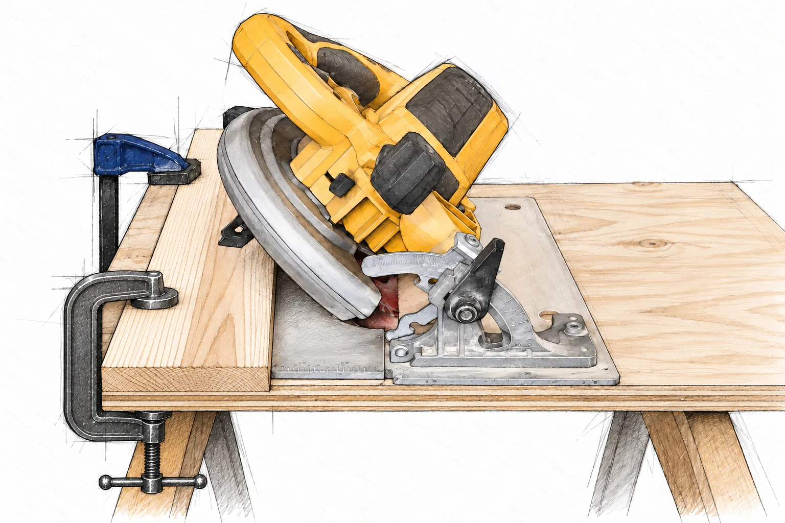
A x 1 / C x 2 / Circular saw, guide and clamps
Cut the waterfall joints · Hollow Panel Waterfall Console
Cut the long points accurately
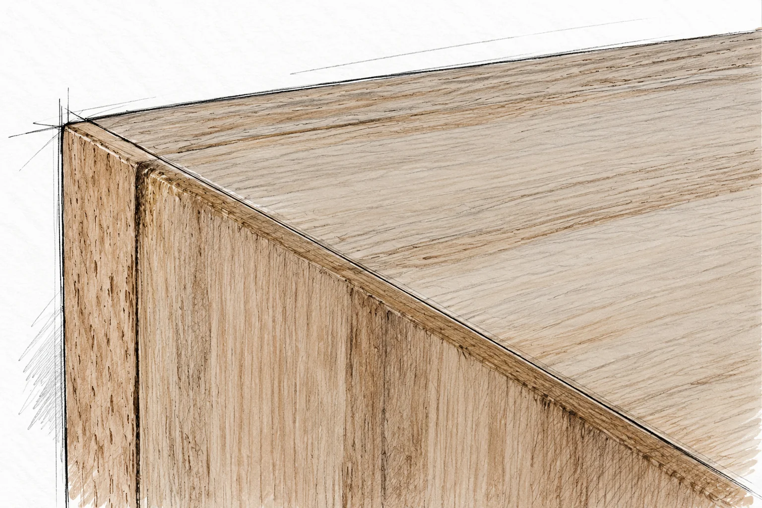
Test a 45-degree bevel on scrap. Mark A and C on their outside faces, support the plywood fully and cut on the waste side. The top bevels meet the side bevels to make two square upper corners.
Keep the setup clear
The guide must not move. Clamp it across the guide and plywood with opposing pads, outside the saw path. Keep the saw shoe flat on the panel. The sketch omits the operator; use both prescribed grips during the actual cut.
STEP 01 / POCKET-HOLE PREPARATION
Drill before assembly
Plywood pockets
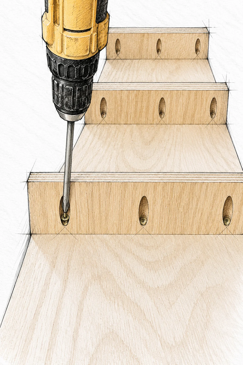
Use the 3/4 in / 19.1 mm material setting. Drill three pockets at each short end of B. Drill three along one 11 3/4 in long edge of every E and F support rib, with the screw path exiting through the edge that meets its receiving panel.
Center support pockets
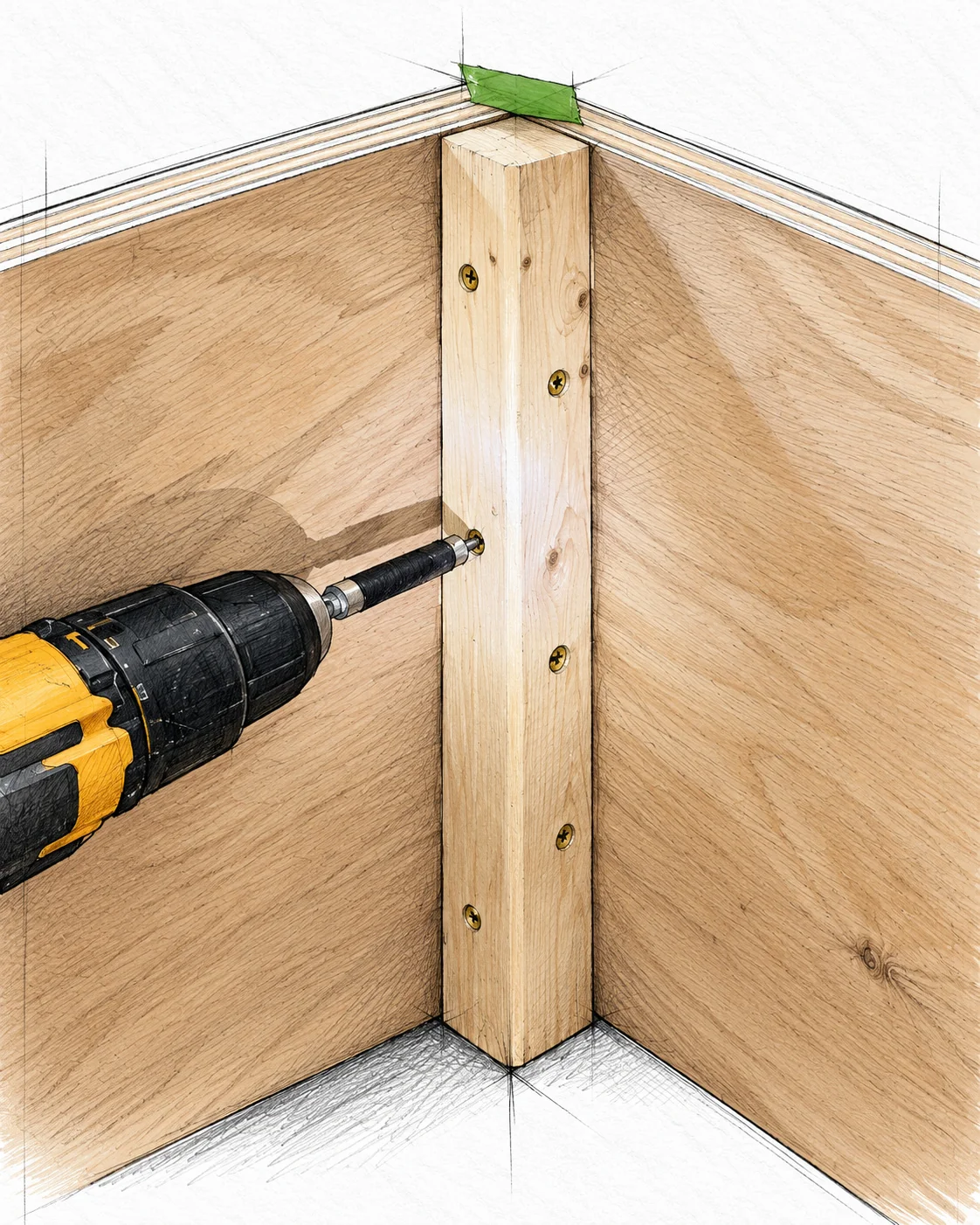
Identify one G cleat as the center top support. Drill two pockets at each of its short ends using the 3/4 in setting for the 3/4 in receiving face trim. This is not the usual same-thickness 2x2 joint: verify the jig setup and 1 1/4 in screw path on scrap first.
Keep the screws accessible
Mark the hidden faces and the final front and back. The center-support end pockets must remain accessible after the support is attached beneath A. Do not drill these pockets in the two corner cleats; they use straight wood screws.
Count the planned connections
These locations total 37 pocket screws: 6 at B ends, 9 in E ribs, 18 in F ribs and 4 at the center support. Keep extra screws for scrap setup and damaged fasteners.
STEP 02 / LOWER PLINTH
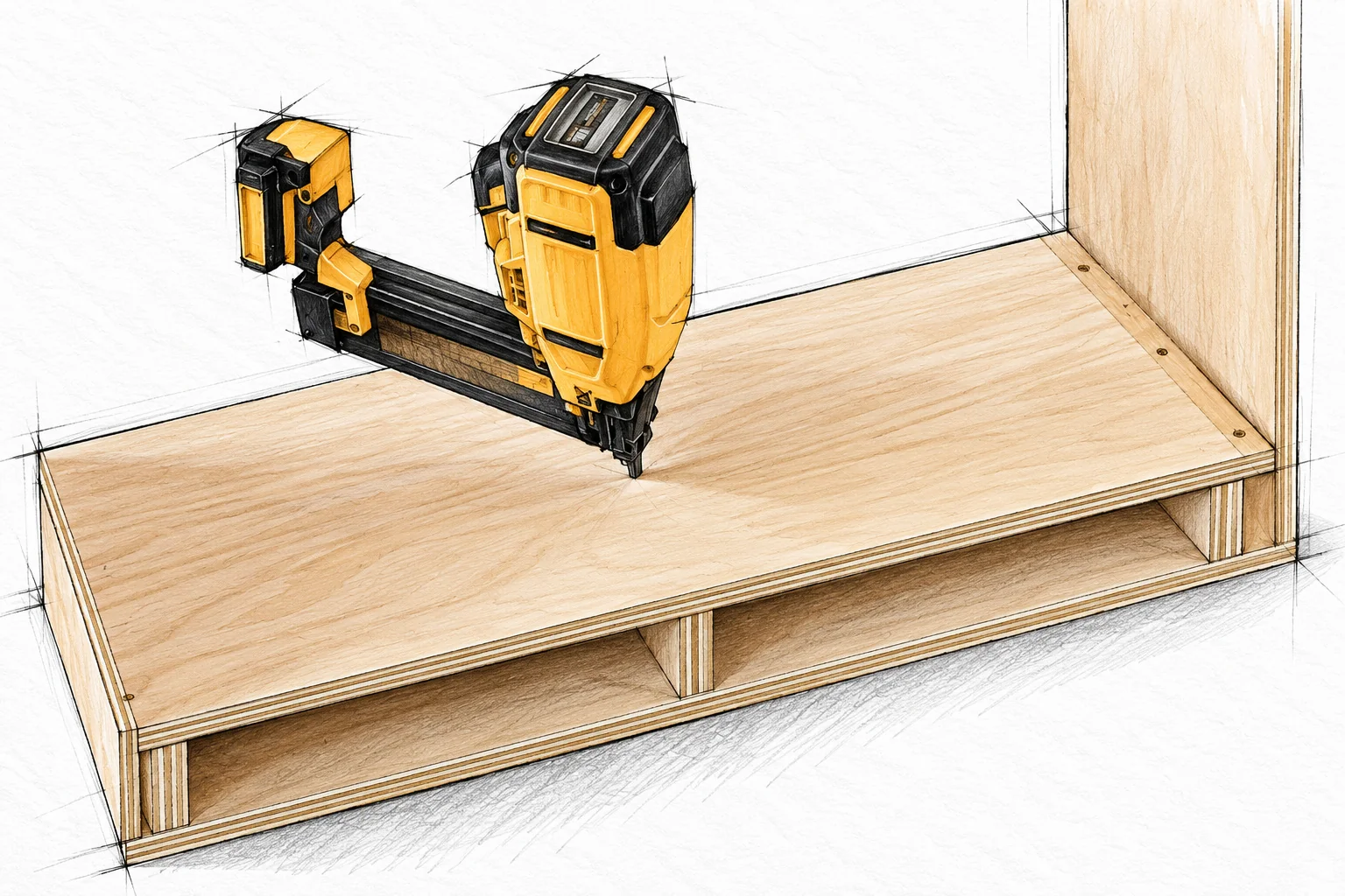
Attach the bottom ribs
B x 1 / E x 3 / Glue and 1 1/4 in pocket screws
Attach the bottom ribs · Hollow Panel Waterfall Console
Work on the hidden underside
Lay B on a protected surface with its underside up. Stand the three E ribs on their 11 3/4 in edges, perpendicular to B. Space them evenly along the length; their exact spacing is not critical.
Fasten without twisting
Keep each rib square and its full edge seated in glue. Drive three pocket screws per rib. When turned upright, the 2 3/4 in ribs and 3/4 in panel put the top of the bottom panel 3 1/2 in / 88.9 mm above the floor.
STEP 03 / OUTER SHELL
Set the side height
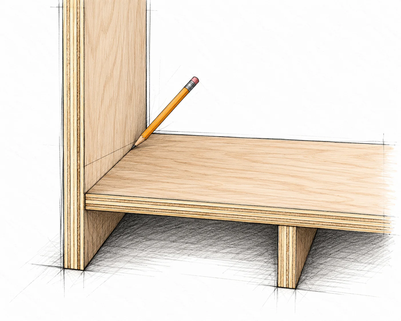
C x 2 / B assembly / Glue and six 1 1/4 in pocket screws
Set the side height · Hollow Panel Waterfall Console
Transfer the height
Set the bottom assembly on its ribs. Stand one C beside it with its square end on the floor and its bevel at the top. Mark the top surface of B on the inside of C. Repeat for the opposite side.
Attach the two sides
Align B to these marks and keep all front and back edges flush. Glue the B-to-C joints and drive the predrilled end pockets. Compare diagonals and check both sides square before the glue sets.
STEP 04 / TOP CORNERS
Reinforce the bevel joints
A x 1 / Two G corner cleats / Glue and twelve 2 in screws
Reinforce the bevel joints · Hollow Panel Waterfall Console
Close the upper corners
Fit A between the two beveled side tops. Align the outside edges and tape the joints while checking that both corners close at 90 degrees. Seat a G cleat against the two inside faces of each corner.
Drive from the cleat into the skins
Glue and fasten each cleat with three 2 in screws toward the top and three toward the side. Stagger the two rows so their paths do not intersect. Use suitable pilot holes and stop before the heads crush the wood.
STEP 04 / CENTER SUPPORT
Support the top trim
Position the remaining G
Center the third 11 3/4 in cleat under A, running from front to back. Keep its short ends flush with the plywood edges so they can meet the two top face-frame rails. The nominal gaps to the corner cleats are about 27 in / 685.8 mm.
Attach it to the top
Apply glue at the top contact face. Drive three 2 in wood screws through G into A. The screw penetration must remain within the top skin. Leave the two pockets at each short end facing outward and accessible.
Keep the final connections for later
After the face frames are nailed on, these four end pockets receive 1 1/4 in pocket screws into the top front and back trim. Do not block the pockets or substitute screws that emerge through the visible trim.
STEP 05 / HOLLOW SIDE SKINS
Close the inner sides
F x 6 / D x 2 / Glue, 1 1/4 in pocket screws and 1 1/2 in nails
Close the inner sides · Hollow Panel Waterfall Console
Add three ribs per side
Attach the F ribs to each outer side with glue and pocket screws. Set one on B, another about 12 in / 304.8 mm above B and another about 22 in / 558.8 mm above B. Keep the ribs clear of the corner cleats.
Nail only into backing
Align each D with the top surface of B and seat it against the ribs. Glue and nail D into those ribs. Mark their positions first: the nailer nose must contact the skin directly over solid backing, never the hollow gap.
STEP 06 / FRONT AND BACK TRIM
Fit the mitered face frames
H x 4 / I x 4 / 1 1/2 in brad nails / Four pocket screws
Fit the mitered face frames · Hollow Panel Waterfall Console
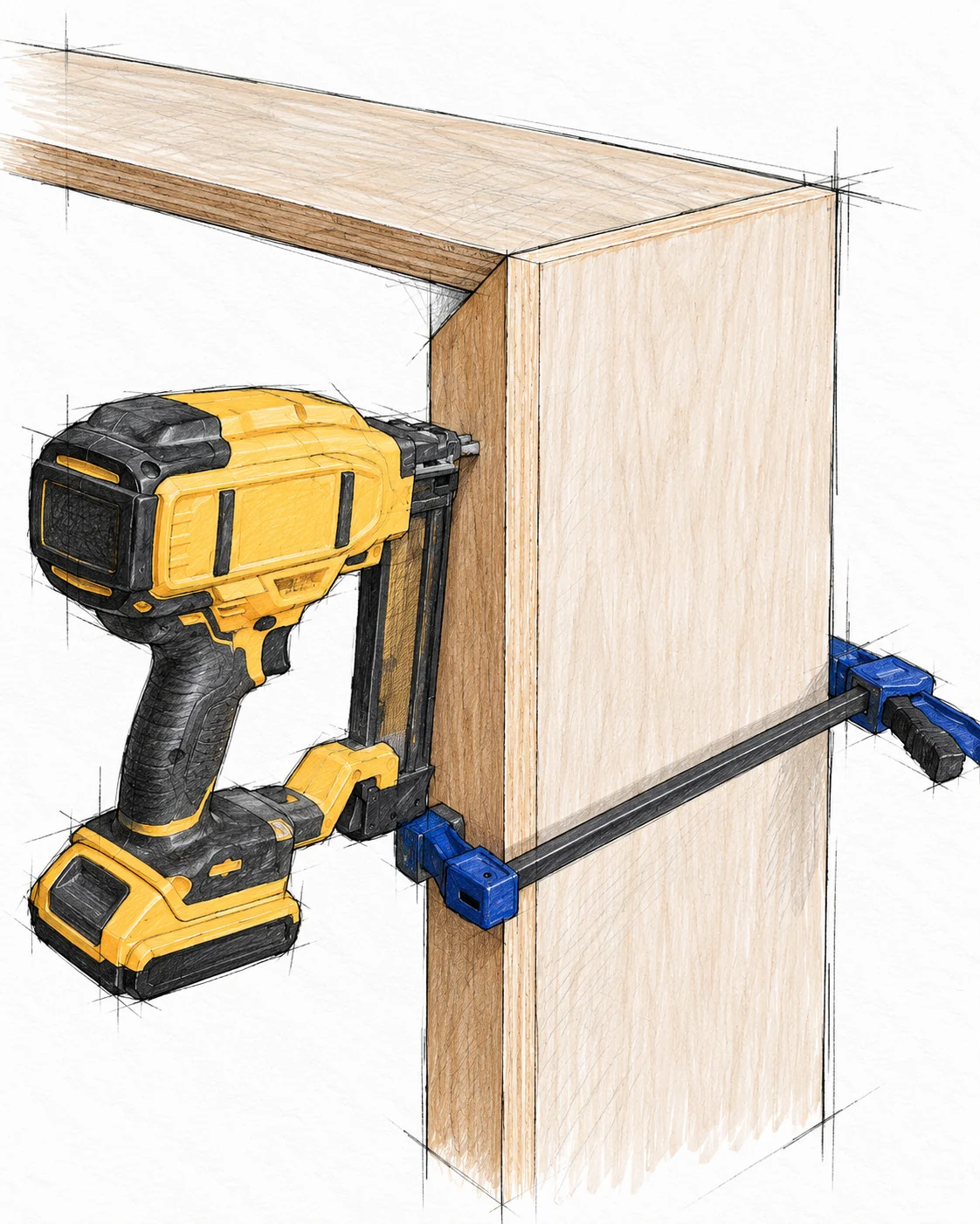
Fit one piece at a time
Start with a bottom I, then the two H stiles, then a top I. Trim the 45-degree miters gradually for a closed fit with flush outside edges. Repeat on the opposite face; both frames have the same outer size.
Aim through trim into the shell
Clamp with padded opposing jaws and drive nails through the trim into the plywood edges or cleats behind it. Keep the nose off the broad side face. Finally drive the four center-support pocket screws into the two top trim rails.
STEP 06 / FIRST FACE INSPECTION
Check the front frame
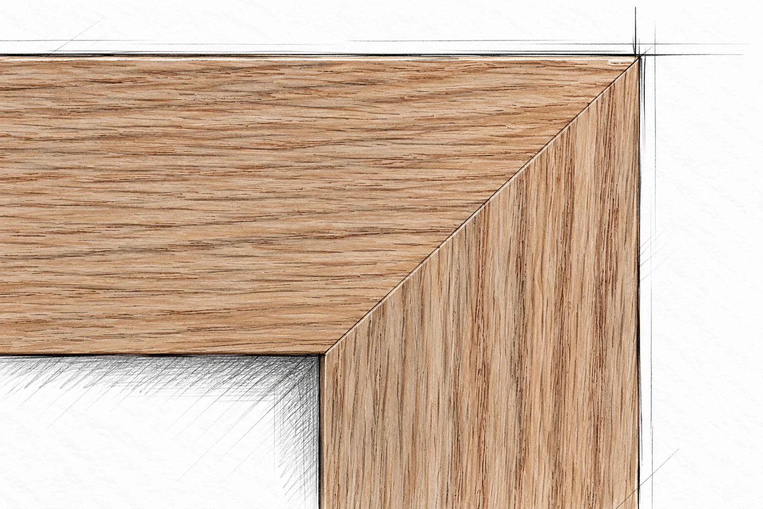
First face frame / Four closed miter corners
Check the front frame · Hollow Panel Waterfall Console
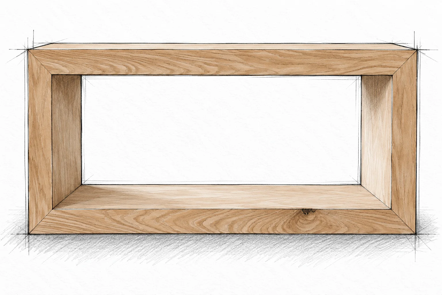
Check continuity around the opening
The four trim pieces form one rectangular frame. Check that the bottom rail reaches the floor, the top rail aligns with A and the stiles cover the hollow side edges. All four miters should close without forcing the shell.
Inspect the grain and surface
A pronounced cathedral grain is one possible face arrangement. The grain is cosmetic; do not use weak, split or loose knots at fastener locations merely to match a pattern.
STEP 06 / REVERSE FACE INSPECTION
Check the second frame
Opposite face frame / Center support fastened at both ends
Check the second frame · Hollow Panel Waterfall Console
Inspect the other face separately
The opposite frame must be just as square and flush. Quieter, straighter grain can give it a different appearance without changing any dimensions. Inspect every miter, rather than assuming the first face proves the second is aligned.
Confirm the hidden work
Before finishing, verify the center support is fastened into both upper trim rails. Look underneath and check every cleat, pocket screw and skin-to-rib connection for a secure, fully seated fit.
STEP 07 / SURFACE PREPARATION / BEFORE FILLING
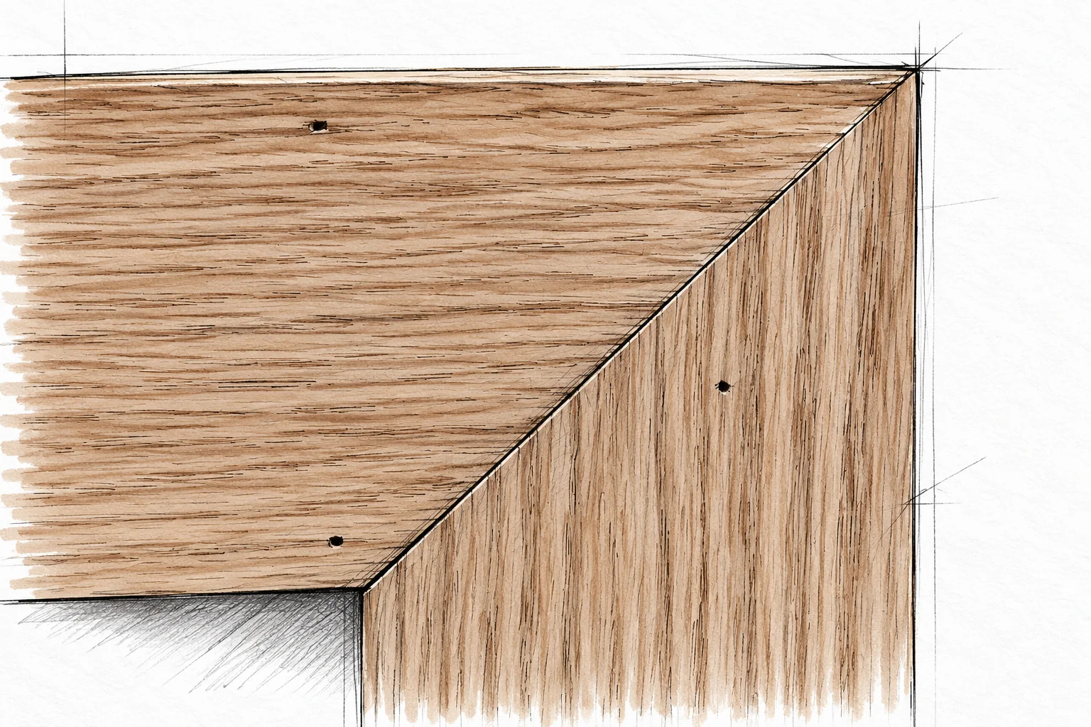
Find small surface defects
Nail holes and small miter gaps / Compatible wood filler
Find small surface defects · Hollow Panel Waterfall Console
Inspect under angled light
Mark small nail holes and cosmetic seam gaps. Check that each joint is secure first. A large open joint, loose trim or misaligned shell needs refitting, not a thick layer of filler.
Test the color response
Use matching offcuts to test filler with the complete finish. Filler can accept stain differently from oak. Keep it local to the defect instead of spreading it across the surrounding grain.
STEP 07 / SURFACE PREPARATION / AFTER FILLING
Fill and let it dry
Filled nail holes / Closed cosmetic seams
Fill and let it dry · Hollow Panel Waterfall Console
Apply a small amount
Press suitable filler into the nail holes and minor gaps. Follow the product instructions for application thickness and drying. Remove excess without rounding the crisp mitered edge.
Recheck before sanding
Allow the filler to dry fully. Look again for shrinkage or remaining pinholes, and touch up only where needed. The finished corner should stay straight, square and firmly joined.
STEP 07 / LEVELING / BEFORE SANDING
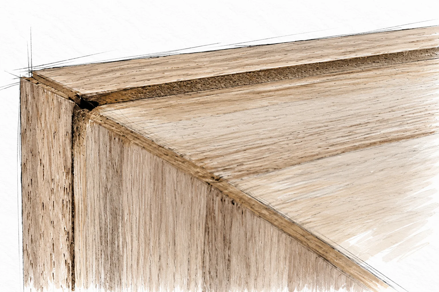
Locate any proud trim
Solid face trim slightly above plywood / Sanding block
Locate any proud trim · Hollow Panel Waterfall Console
Feel for a small ridge
Run a straightedge across the trim and top skin. If the solid trim is only slightly proud, mark that high area. Refit a major mismatch rather than sanding the whole veneered top down to it.
Protect the plywood face
The visible oak veneer is thin. Keep coarse abrasion on the high solid-wood trim only and check often. Do not round the outside corner or sand through the face layer.
STEP 07 / LEVELING / AFTER SANDING
Leave a flush surface
Leveled solid trim / Smooth oak veneer
Leave a flush surface · Hollow Panel Waterfall Console
Refine the surface gently
Once the trim is flush, sand the remaining surfaces lightly with 120, then 180, then 220 grit as appropriate for the finish. The aim is a smooth surface without erasing the edge definition.
Remove every trace of dust
Vacuum with a soft brush and wipe as directed by the finish manufacturer. Inspect for glue residue, sanding scratches and bare spots before opening the stain.
STEP 08 / COLOR COAT
Apply the dark stain
Compatible conditioner and black stain / Oak test piece
Apply the dark stain · Hollow Panel Waterfall Console
Follow one compatible finish system
Test the conditioner, stain and intended protective finish together. Apply the conditioner and re-sand raised grain only as directed. Apply the black stain evenly to the prepared oak.
Let the stain dry
Keep the console on a clean protected surface with ventilation. Follow the current product drying times, not a fixed clock estimate. Inspect the unhighlighted black finish before deciding whether to add grain wax.
STEP 08 / OPTIONAL GRAIN HIGHLIGHT
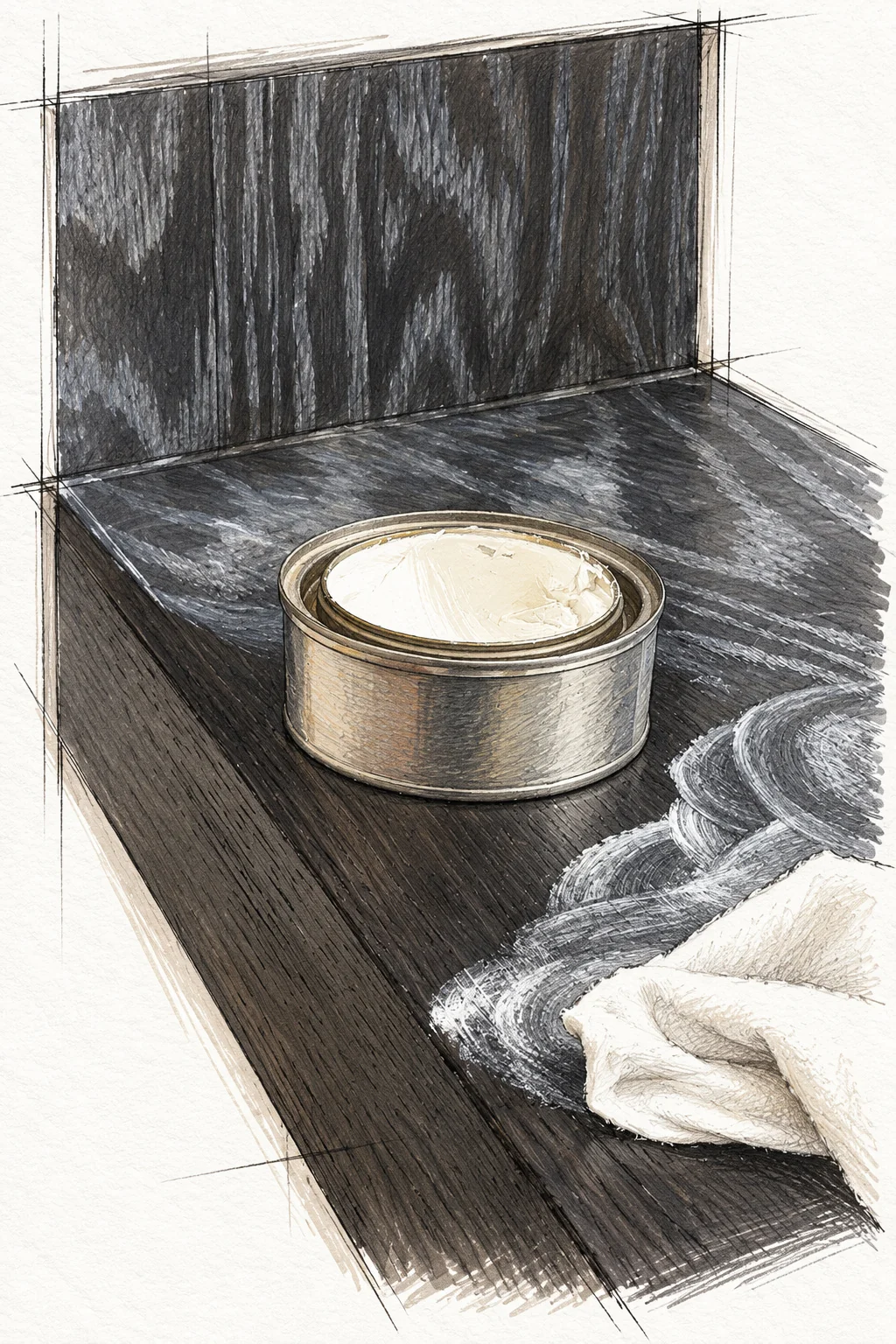
Work wax into the grain
Compatible pale grain-highlighting wax / Clean cloths
Work wax into the grain · Hollow Panel Waterfall Console
Test before the visible surfaces
Use an oak offcut or hidden area to confirm compatibility and the amount of pale grain contrast. This effect relies on open oak pores and will not look the same on smooth, closed-grain wood.
Apply and remove the excess
Buff the wax into the surface, then wipe across the grain after the product's stated dwell time. Leave pale material in the pores, not a thick cloudy film on top. Use only a finish combination approved by its manufacturer.
STEP 08 / FINISHED SURFACE DETAIL
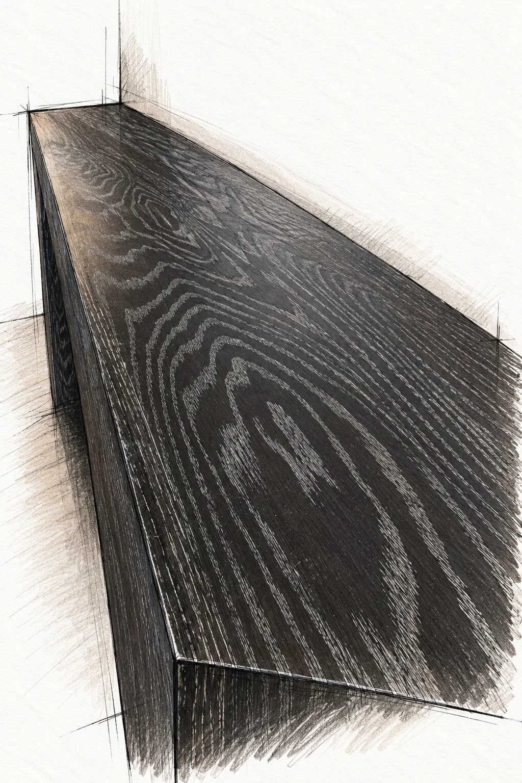
Inspect the grain contrast
Pale pores over charcoal oak / Cured finish
Inspect the grain contrast · Hollow Panel Waterfall Console
Look along the light
Check the top and both faces for an even sheen, clean corners and consistent grain highlighting. Remove smears with the method approved for the chosen product before it cures.
Let the surface cure
Do not add a clear film over wax unless that combination is expressly approved. Allow full curing before placing objects on the console. Keep wet containers, abrasive objects and hot items off the finish.
FINISH AND INSPECT
Final checks and care
Inspect the complete assembly
Verify the top, bottom and both hollow sides are secure. All nails should be seated without exposed points, and all fasteners should stay within the wood. Check for rocking, loose joints and damaged veneer before use.
Secure the furniture
Place the console on a level floor. Fit an appropriate anti-tip restraint to a solid internal cleat or other verified structural location and to suitable wall framing or anchors. Do not attach a restraint only to decorative trim or a hollow area.
Use it as a display console
No load capacity is established by this guide. Do not sit, stand or climb on it, and do not assume it supports an aquarium, stone top or heavy equipment. Keep heavy objects low and away from the front edge.
Maintain the finish
Clean with products approved for the coating. Protect the surface from standing water and heat. Inspect fasteners, restraint and finish periodically, and stop using the console if a joint loosens or the structure is damaged.
 FREE WOODWORKING PLAN