WOODWORKING · DIY · A HANDMADE HOME @grainbyjoy
GRAIN by JoyWOODWORKING PLANS · WORKSHOP STORIES · HOME
FIND YOUR NEXT GOOD THING
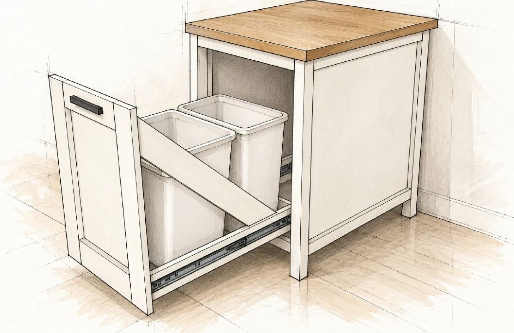
WOODWORKING PLANPullout Bin Kitchen Island
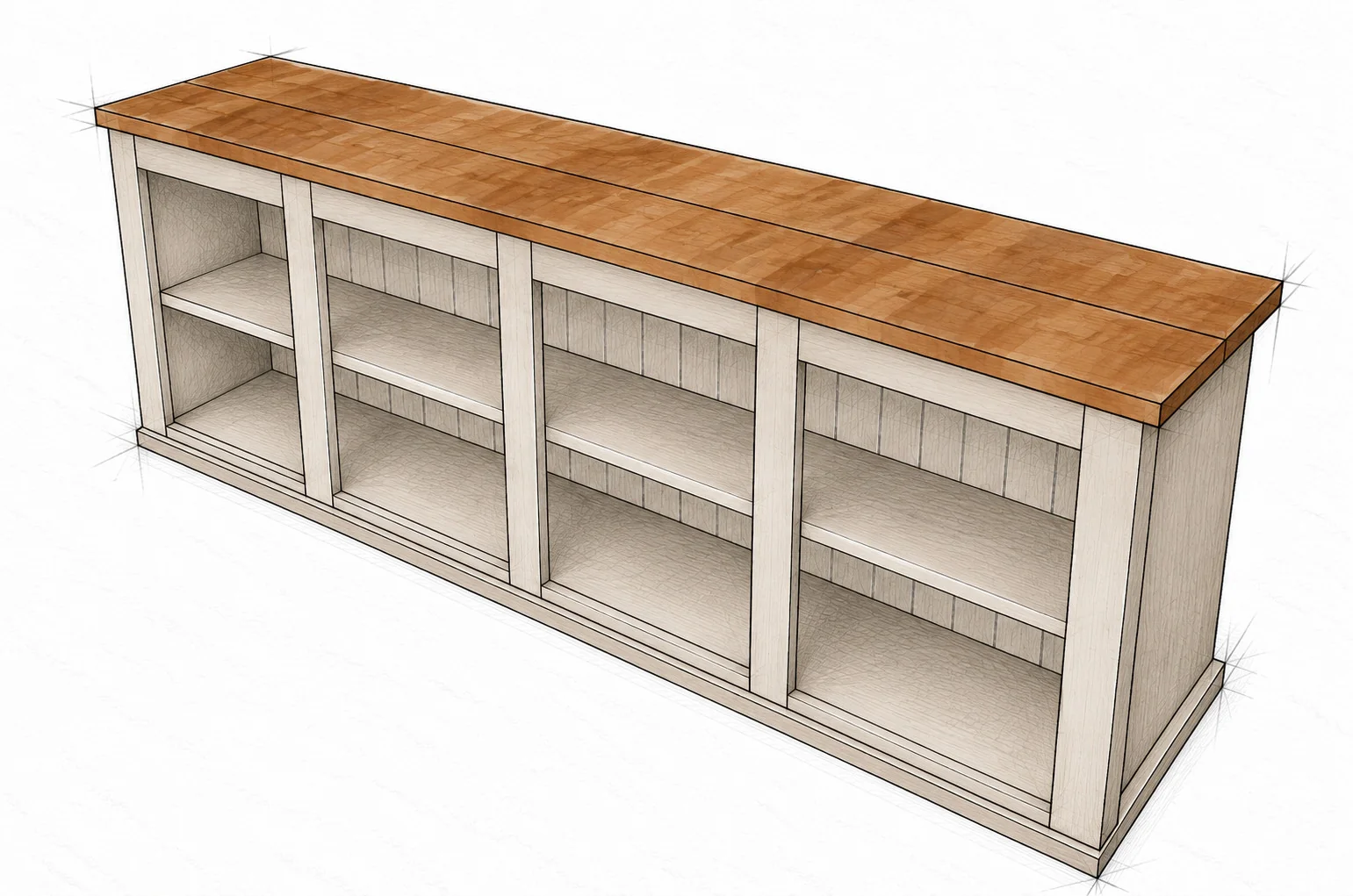
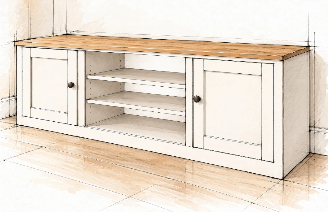
WOODWORKING PLANFarmhouse Media Console
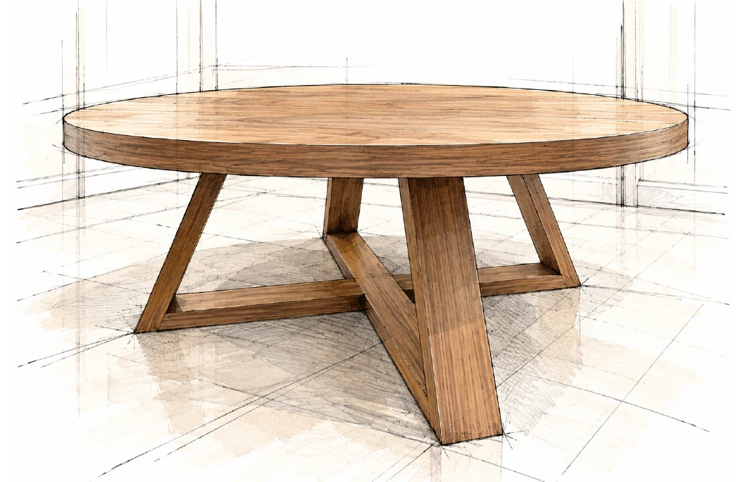
WOODWORKING PLANRound Coffee Table
WOODWORKING PLANGeometric Hairpin Coffee Table
WOODWORKING PLANHollow Panel Waterfall Console
WOODWORKING PLANFarmhouse Console Table
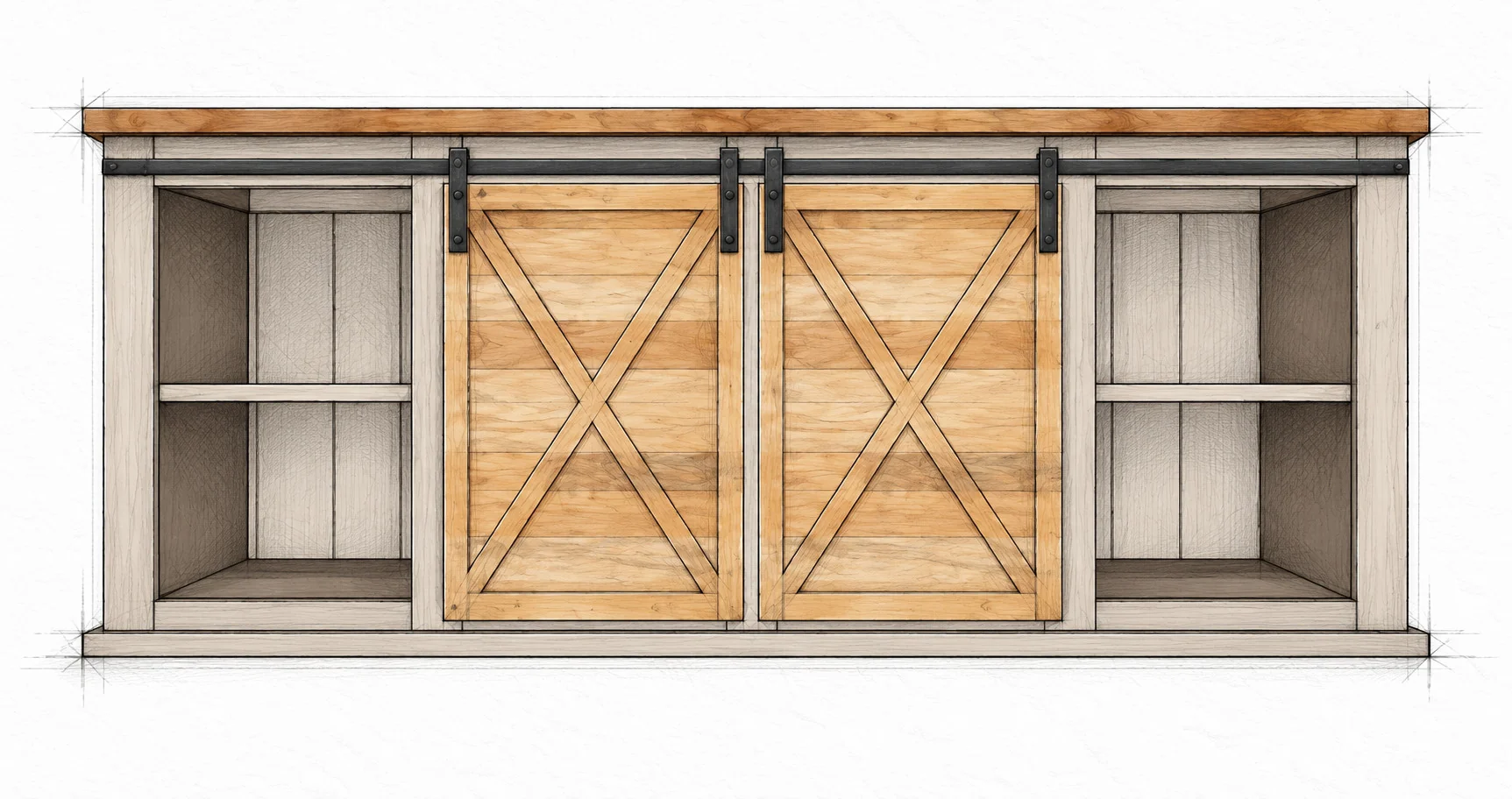
WOODWORKING PLANBarn Door Console
WOODWORKING PLANBeginner Farm Table
WOODWORKING PLANFarmhouse Coffee Table
Barn Door ConsoleFREE WOODWORKING PLAN
Storage / INTERMEDIATE

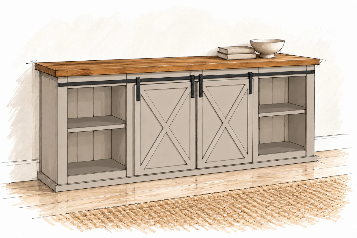
Barn Door Console

A generous four-bay console with open storage and two sliding doors.

FINISHED DIMENSIONS91 × 18 3/4 × 37 1/2 in
SKILL LEVELIntermediate
WHAT IS INCLUDEDMaterials, cut list and illustrated steps
Read the free planMade this plan? Share your build
A GOOD BUILD STARTS WITH A CLEAR PLAN
  • Materials and tools
  • Cutting information and dimensions
  • Illustrated assembly steps
FROM THE FIRST CUT TO THE LAST DETAIL

Take it one step at a time

Everything you need to follow this build is written below. Read the materials, measurements and construction notes before your first cut.

Read the build steps

Yes. The complete plan is available to read on this page.
THE FREE BUILD GUIDE

Barn Door Console

A generous four-bay console with open storage and two sliding doors.

BEFORE THE FIRST CUT

Materials

Select straight, dry boards. All full-length boards below are 8 ft / 96 in (2438.4 mm) unless noted.

QuantityNominal stockPurpose
6 boards2×3Top and bottom frames
4 boards1×4Front face frame
2 boards1×8Bottom and middle shelves
2 boards1×10Bottom and middle shelves
4 boards1×2Shelf supports, cleats and trim
2 boards2×10Two-board top
2 panels3/4 in thick36 × 17 1/4 in 914.4 × 438.2 mm sides
1 sheet1/4 in plywood or hardboard4 × 8 ft / 1219.2 × 2438.4 mm Back cut to fit

Why four 1×2 boards

Reserve one board for the 90 in (2286.0 mm) front trim. The remaining short parts total 192 1/2 in (4889.5 mm), so two more 8 ft boards are insufficient even before saw kerf. Buy four in total.

HARDWARE AND CONSUMABLES

Fasteners and door materials

Resolve the door system before cutting its parts. Do not select hardware by appearance alone.

ItemQuantity or specification
Sliding-door hardware1 complete two-door cabinet kit, compatible with the door size, total thickness and weight; include all specified stops, guides and anti-jump parts.
Door blanks2 panels, cut to fit; approximately 20 × 30 in (508.0 × 762.0 mm) each. A 1/2 in (12.7 mm) plywood core is one option only.
Door overlay stripsEnough for 2 perimeter frames and 2 X details; widths, thicknesses and lengths depend on the verified door design.
Frame and top screws2 1/2 in (63.5 mm) wood screws, or the compatible pocket-hole screws for that joint method. Quantity and gauge depend on the chosen fixing pattern.
Finish nails1 1/4 in (31.8 mm) for face, supports and trim; suitable longer nails for bottom shelf if needed. 3/4 in (19.1 mm) nails can suit the back.

Also allow wood glue, abrasive papers, filler, compatible paint or stain and clear finish, plus a wall anti-tip restraint suitable for the cabinet and wall. Verify every fastener path on scrap; no tip may emerge.

SET UP THE WORKSHOP

Tools and preparation

This is an intermediate build. A novice should get experienced help with saw setup, large assemblies and the sliding-door system.

Measuring and assembly

Tape measure, pencil, square, long straightedge, level, clamps, drill/driver, drill and countersink bits, nailer or suitable hand-nailing tools, and a sander. A pocket-hole jig is optional for the frames and face frame.

Cutting tools

Use a compound miter saw for crosscuts and trim miters. Use a table saw or a guided circular saw with full sheet support for panel work. Optional narrow back strips and angled X details need additional careful fitting.

Advanced operations

Mitering trim, ripping narrow strips, fitting the door X details and mounting sliding hardware require tool-specific setup. Do not freehand a rip cut. Use guards, a riving knife and appropriate push aids where applicable; never trap a small offcut.

Safety before every operation

Wear eye and hearing protection, use dust extraction and suitable respiratory protection, and clamp work securely. Disconnect power before adjustments. Keep hands clear of the blade and nail path. Follow each tool maker’s instructions.

Read the drawings correctly

Sketches explain the assembly, not machining tolerances or hardware clearances. Use the written dimensions and your measured stock; never scale the art. Label every part, cut a test piece, then dry-fit before gluing.

PARTS A TO H

Cut list for the cabinet

Lengths are in inches with exact conversions rounded to 0.1 mm. Square ends unless a later note says otherwise.

PartQtyStockLength inmmUse
A42×3842133.6Long frame rails
B42×317431.8Frame end caps
C42×314355.6Inner crosspieces
D23/4 in panel36 × 17 1/4914.4 × 438.2Sides
E51×436914.4Face stiles
F81×417 3/4450.9Face rails
G21×8872209.8Shelf planks
H21×10872209.8Shelf planks

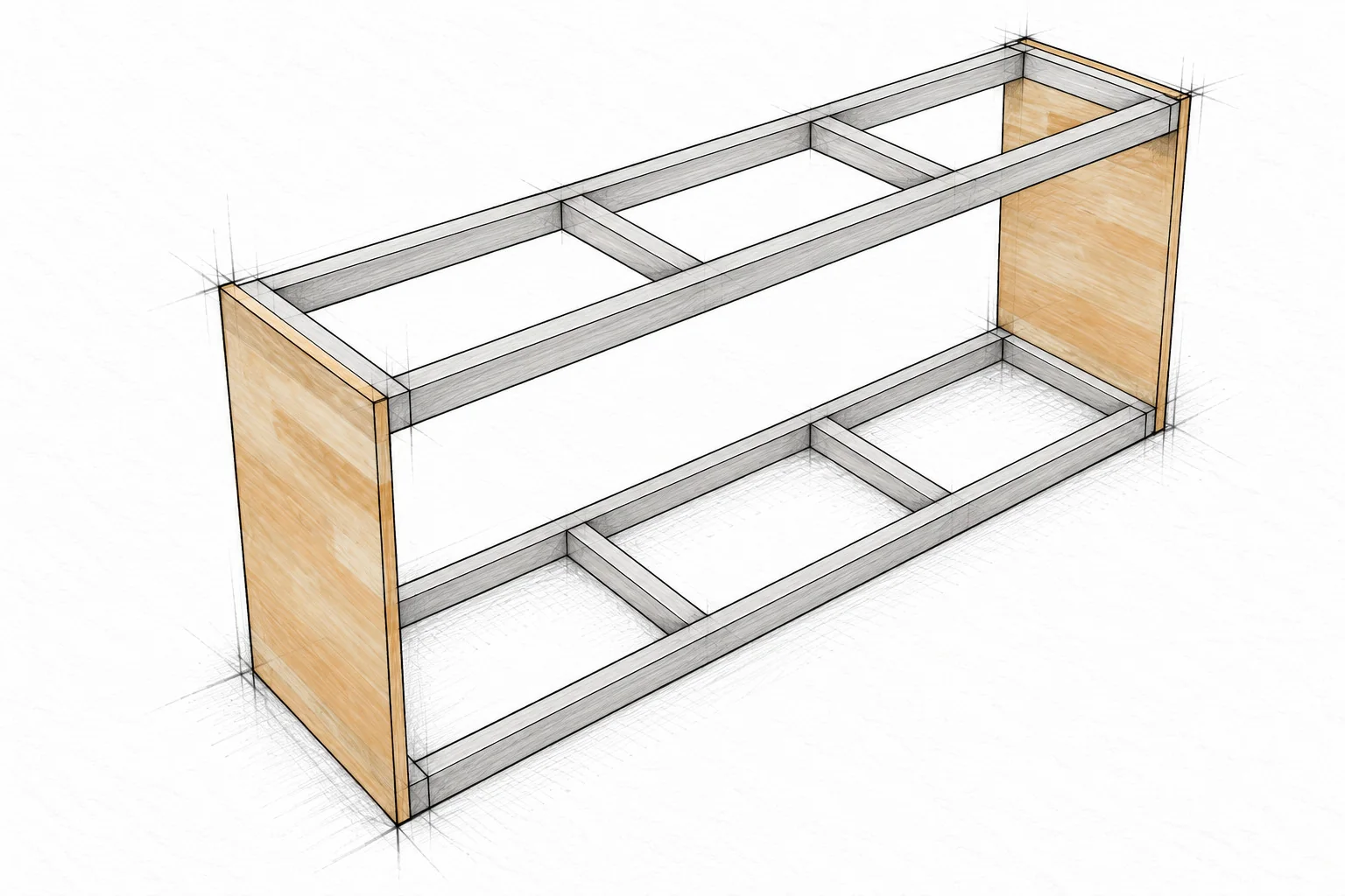
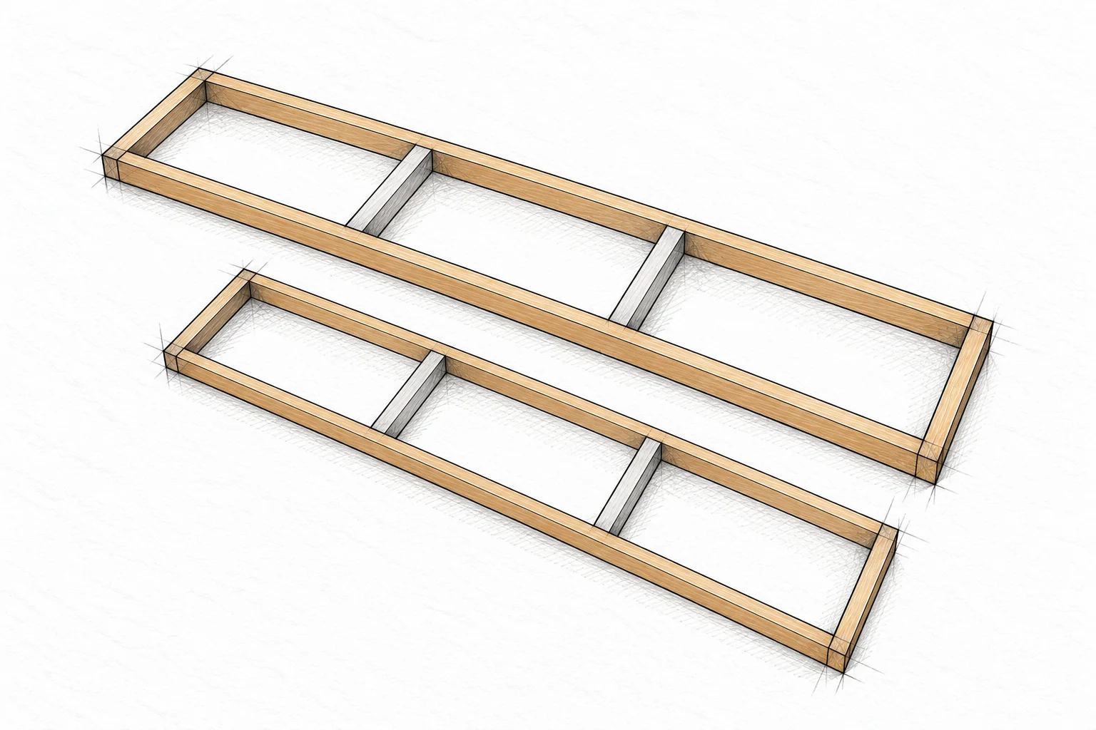
Make two equal frame sets

Each frame uses A × 2, B × 2 and C × 2. B caps the ends of the long rails; do not put B between them. The completed frame is 87 × 17 in (2209.8 × 431.8 mm).

PARTS I TO O

Cut list for the finishing parts

Cut trim and doors after checking the assembled cabinet. Keep the longest-point convention for all trim miters.

PartQtyStockLength inmmUse
I51×214355.6Vertical supports
J51×217431.8Shelf cleats
K11×2902286.0Front base trim
L21×218 3/4476.3Side base trim
M22×10912311.4Top planks
N1 set1/4 in panel36 high Width to fit914.4 highBack panel or strips
O2Door stockAbout 20 × 30 Fit to hardwareAbout 508.0 × 762.0Sliding doors

K and L have mitered corners

K has two opposing 45° end cuts, not parallel; its outer face is the long face. Each L has one 45° front end and one square rear end. Dry-fit the pair of front corners before trimming to final length.

MEASURE THE WOOD YOU BUY

Nominal and actual sizes

Nominal lumber labels are not the finished cross-sections. These are typical dry, surfaced dimensions; local stock may differ.

NominalActual cross-section inActual cross-section mm
1×23/4 × 1 1/219.1 × 38.1
1×43/4 × 3 1/219.1 × 88.9
1×83/4 × 7 1/419.1 × 184.2
1×10³/4 × 9 1/419.1 × 235.0
2×31 1/2 × 2 1/238.1 × 63.5
2×101 1/2 × 9 1/438.1 × 235.0

Panel thickness matters

Side panels are specified at 3/4 in (19.1 mm), the back at 1/4 in (6.4 mm), and the optional door core at 1/2 in (12.7 mm). Plywood sold under these names can be thinner; measure it before laying out flush edges.

Allow for every saw cut

Mark the waste side and include the blade kerf between parts. Four 2×3 boards each yield one A; the other two each yield two B and two C. Keep offcuts only where sound and long enough for the chosen operation.

CHECK THE ASSEMBLED PROPORTIONS

Dimension checkpoints

These calculations use the actual lumber sizes on the previous page. Recheck if your stock differs.

AssemblyDimension inmm
Each support frame87 wide × 17 deep2209.8 × 431.8
Body with side panels88 1/2 wide × 36 high2247.9 × 914.4
Four front openings17 3/4 wide × 29 high450.9 × 736.6
Body depth including face18457.2
Base trim overall depth18 3/4476.3
Two-board top91 wide × 18 1/2 deep2311.4 × 469.9
Height including top37 1/2952.5

Top and base are different depths

Set the top flush to the back: its front projects 1/2 in (12.7 mm) beyond the face, versus 3/4 in (19.1 mm) for the base trim. Center it for 1 1/4 in (31.8 mm) overhang at each body end.

Reserve room for the doors

Door hardware and handles may project beyond the base. Measure the completed hardware envelope before placing the console in a walkway or alcove.

STEP 01 / ASSEMBLY

Build the two support frames

A × 4 / B × 4 / C × 4

barn door console — 9 illustration
Build the two support frames · Barn Door Console

1 Lay out on edge

2 Square and screw

Stand each 2×3 on its narrow edge: 2 1/2 in (63.5 mm) tall. Put two A rails between two B end caps. Add two C crosspieces between the rails; divide the length into three 27 in (685.8 mm) clear bays.

Clamp the joints, compare diagonals, then glue and screw with suitable 2 1/2 in (63.5 mm) wood screws. Predrill to prevent splitting. Optional pocket holes use the jig setting for 1 1/2 in stock and its compatible screws.

BEFORE YOU CONTINUE

Make two identical 87 × 17 in frames. Use screws, not nails alone, for these load-supporting joints.

STEP 02 / ASSEMBLY

Attach the two side panels

D × 2 / Two completed frames

barn door console — 10 illustration
Attach the two side panels · Barn Door Console

1 Establish the front

2 Clamp and secure

Stand both frames between the two D panels with their upper and lower edges flush to the panel ends. Align the panels flush with the frame fronts; the panels extend 1/4 in (6.4 mm) behind the frames.

Check the case for square and twist, then glue and attach each panel to both frames. Use suitable panel screws, or finish nails at least 1 1/4 in (31.8 mm) long. Select the length for the actual joint thickness.

BEFORE YOU CONTINUE

Do not blindly reuse 2 1/2 in frame screws through the side: 3/4 in panel + 1 1/2 in end cap is only 2 1/4 in total.

STEP 03 / ASSEMBLY

Fit the front face frame

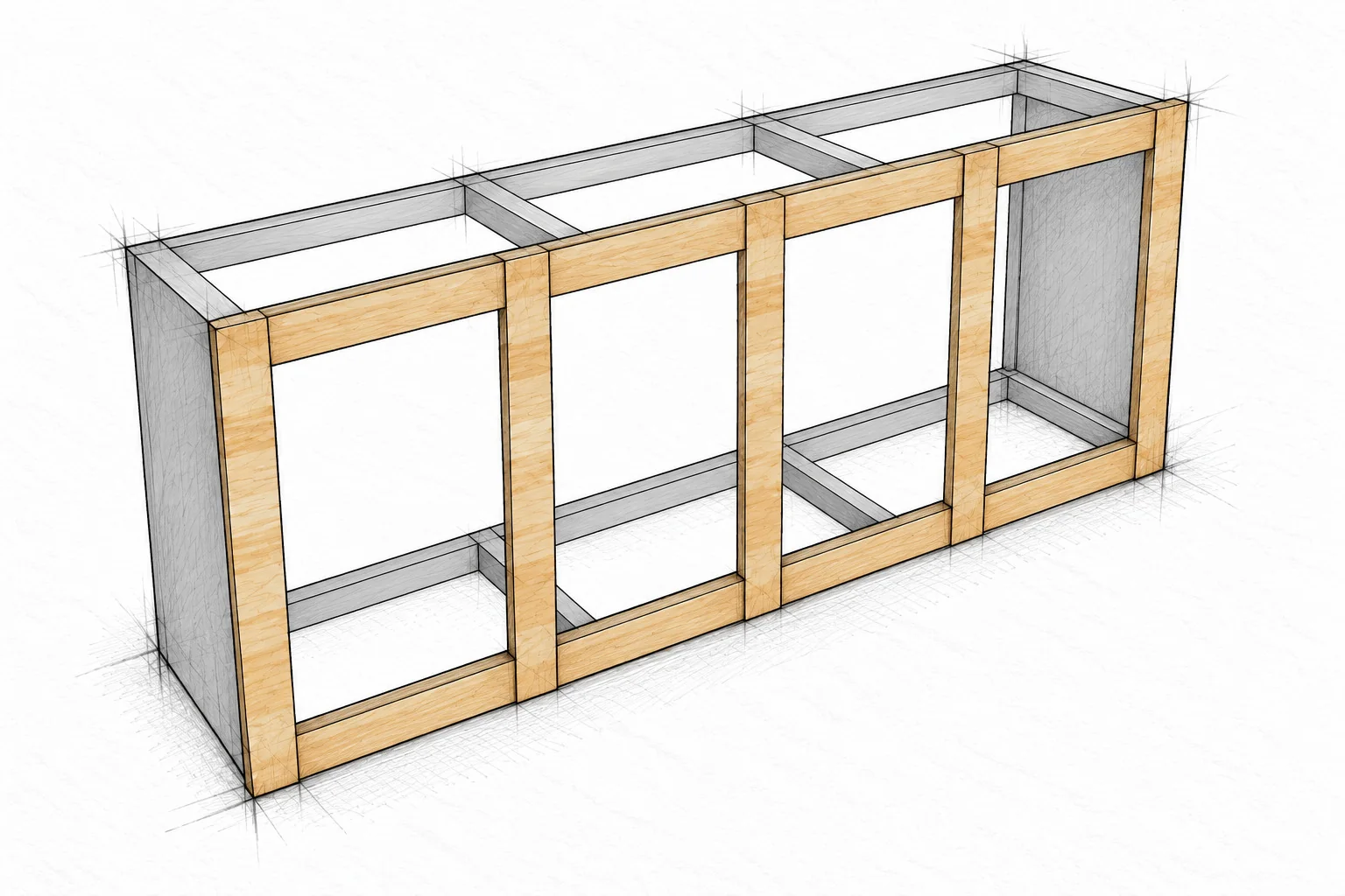
E × 5 / F × 8

barn door console — 11 illustration
Fit the front face frame · Barn Door Console

1 Lay out four openings

2 Fasten without shifting

With help, set the case safely on its back. Lay five full-height E stiles on the front. Fit four F rails along the top and four along the bottom, between the stiles. Keep the outside edges flush.

Clamp and check all four openings before gluing and nailing the face to the support frames with 1 1/4 in (31.8 mm) or suitable longer finish nails. Optional: assemble the face with pocket holes first.

BEFORE YOU CONTINUE

Standard stock gives four equal 17 3/4 × 29 in openings. These stiles are face strips, not full-depth interior dividers.

STEP 04 / ASSEMBLY

Install the bottom shelf

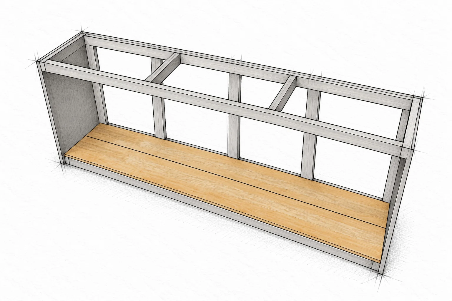
G × 1 / H × 1

barn door console — 12 illustration
Install the bottom shelf · Barn Door Console

1 Dry-lay the two planks

2 Check the depth and attach

Place one G and one H on the lower frame, spanning between the side panels. In the rear view shown, the wider H plank is nearest you. Keep the shelf inside the rear edge of the frame.

The plank widths total 16 1/2 in (419.1 mm). A gap between them can bring the shelf depth to 17 in (431.8 mm). Glue to the frame and nail into the supporting members with suitable nails longer than 1 1/4 in.

BEFORE YOU CONTINUE

Keep the rear 1/4 in side-panel recess clear for the back. Mark frame locations so every nail enters solid supporting wood.

STEP 05 / ASSEMBLY

Add the five shelf supports

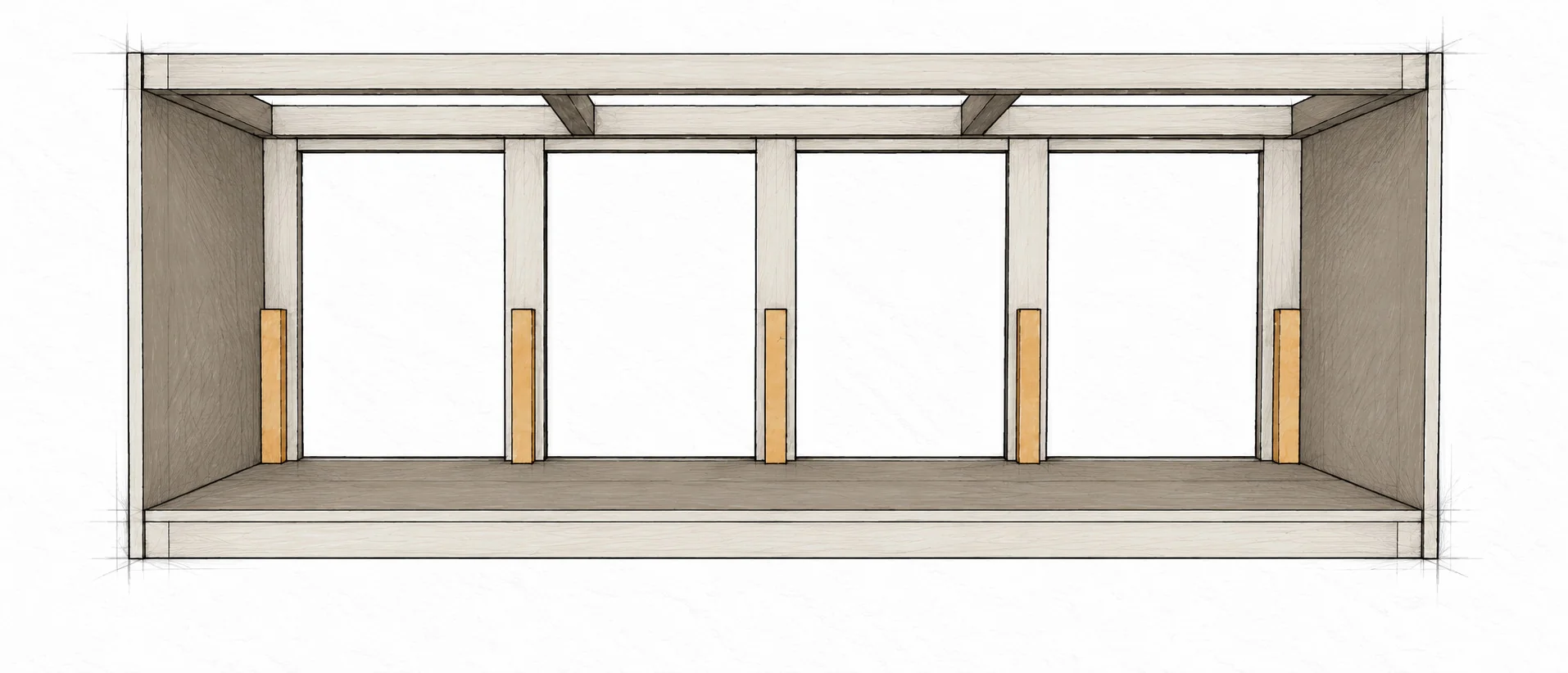
I × 5 / Rear view

barn door console — 13 illustration
Add the five shelf supports · Barn Door Console

1 Mark a common height

2 Attach the supports

Inside the case, position one 14 in (355.6 mm) I support behind each of the five front stiles. Stand its lower end on the bottom shelf and put its broad face against the back of the stile.

Center the three inner supports on their stiles. At the outer stiles, keep each support inside the side panel. Glue and fasten with 1 1/4 in (31.8 mm) finish nails. Check all five tops with a straightedge.

BEFORE YOU CONTINUE

All five supports must bear on the bottom shelf and finish at one level. Their exact positions govern the middle-shelf cleats.

STEP 06 / ASSEMBLY

Assemble the middle shelf

Remaining G × 1 / H × 1 / J × 5

barn door console — 14 illustration
Assemble the middle shelf · Barn Door Console

1 Arrange the planks face down

2 Fit five flat cleats

Lay the remaining G and H on a flat protected bench with their ends aligned. Adjust their gap to match the 17 in (431.8 mm) J cleats. Keep the intended front edge identified.

Lay J across the underside, with the 1 1/2 in (38.1 mm) broad face against both planks. Place one at each end and three inside; transfer the actual support positions from the case. Glue and nail with 1 1/4 in nails.

BEFORE YOU CONTINUE

Five cleats are required. Dry-fit their fronts over all five I supports before glue sets; do not rely on scaled drawing positions.

STEP 07 / ASSEMBLY

Set the middle shelf in place

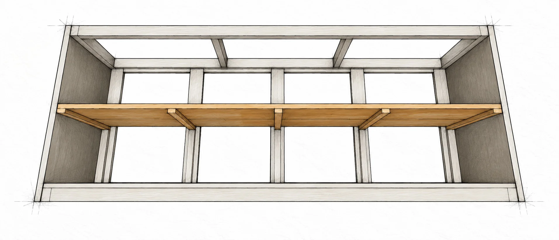
Middle-shelf assembly / Rear access

barn door console — 15 illustration
Set the middle shelf in place · Barn Door Console

1 Lower onto the supports

2 Check and secure

With a helper, bring the shelf into the open case from the rear. Rest the fronts of all five J cleats on the five I supports. Align the shelf with the front; keep its rear flush to the frame rear, leaving the back-panel recess clear.

Confirm the shelf is level and each cleat bears without a gap. Glue the contact areas and secure through the outer side panels and the front stiles into the shelf assembly, keeping fasteners in solid wood.

BEFORE YOU CONTINUE

Do not leave a cleat hanging beside its support. Check nail or screw length on the actual joint so no point enters an open bay.

STEP 08 / ASSEMBLY

Close the back

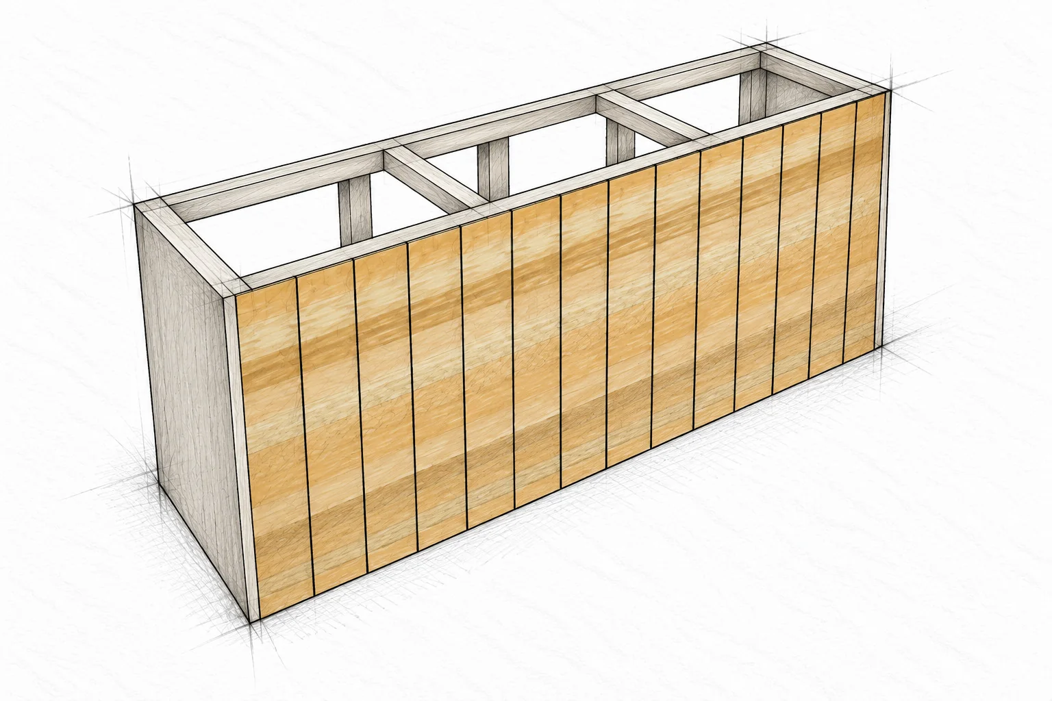
N / 1/4 in panel or fitted vertical strips

barn door console — 16 illustration
Close the back · Barn Door Console

1 Cut the back to the case

2 Square before fastening

Measure between the side-panel rear extensions. Cut a 36 in (914.4 mm) high back to that width. A full panel is simpler; the pictured planked effect uses individual vertical strips cut from the same thin sheet.

Compare the case diagonals, then clamp the back in the rear recess. Nail into the top and bottom frames and into the middle shelf or cleats where supported. A 3/4 in (19.1 mm) nail may suit; check penetration.

BEFORE YOU CONTINUE

Advanced option: rip strips only with safe sheet support and push aids. Do not nail through the thin back where there is no wood behind it.

STEP 09 / ASSEMBLY

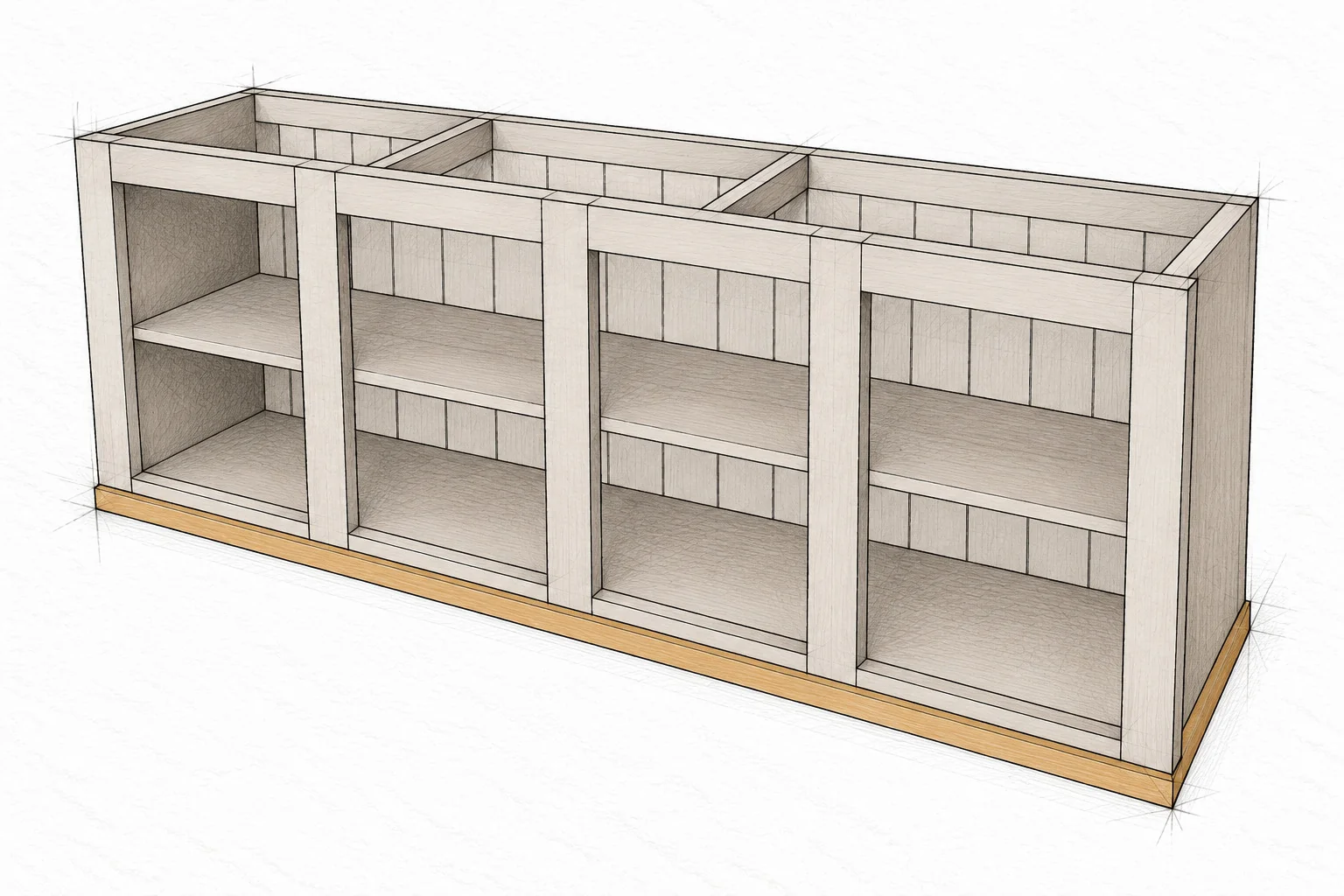
Wrap the base with trim

K × 1 / L × 2 / Advanced miter fitting

barn door console — 17 illustration
Wrap the base with trim · Barn Door Console

1 Fit the front corners

2 Glue and nail

Hold K across the front base, with opposing 45° miters at its ends. Fit each L with a 45° front end and square rear end. Measure the long outer edges and trim gradually until both corners close.

Keep the lower trim edges flush with the cabinet bottom. Clamp gently, then glue and nail the trim with 1 1/4 in (31.8 mm) finish nails. Fill tiny nail holes after the glue dries.

BEFORE YOU CONTINUE

Nominal long-point lengths are 90 in front and 18 3/4 in each side. Test on the built case; never force an open miter closed.

STEP 10 / ASSEMBLY

Fit the two-board top

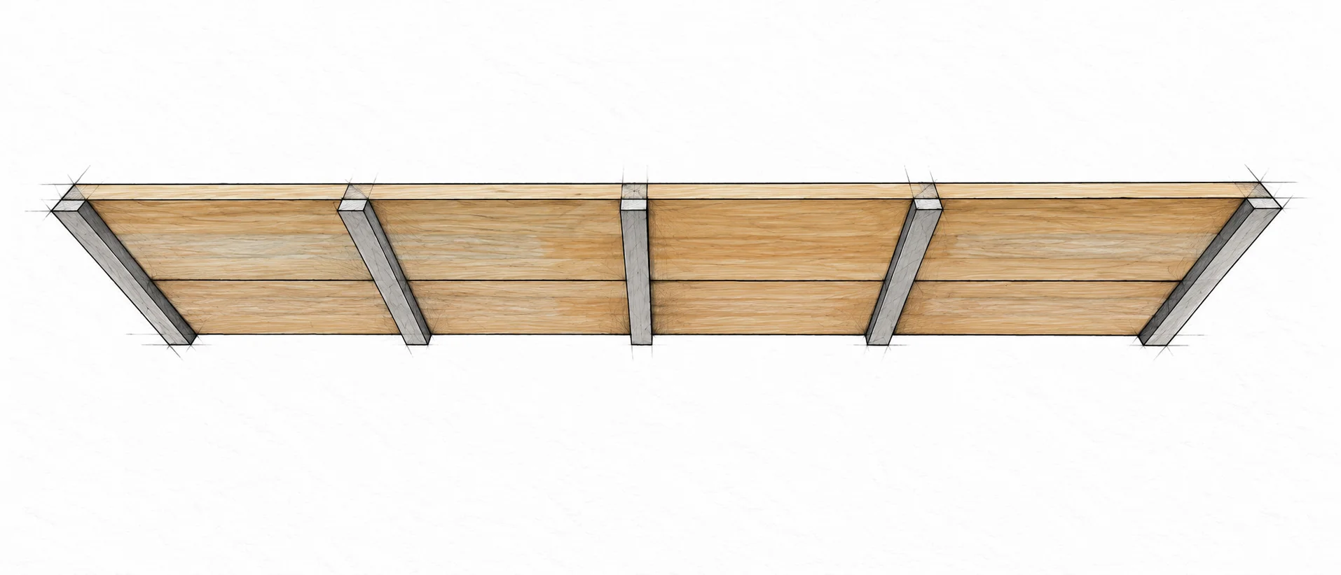
M × 2 / 91 in long

barn door console — 18 illustration
Fit the two-board top · Barn Door Console

1 Align and prefinish if desired

2 Fasten into the upper frame

Lay the two M planks side by side, with matching ends. Put the rear edge flush with the back and center the top left to right. Confirm the top does not interfere with the intended track and hangers.

Prefer movement-tolerant tabletop connectors and their specified screws. For face-fastening, 2 1/2 in (63.5 mm) screws run down into the frame; use a verified clearance-hole detail for cross-grain movement. Do not rigidly glue the top across its width.

BEFORE YOU CONTINUE

Hidden fixings must allow wood movement. Follow their instructions: a 2 1/2 in screw cannot reach through an undrilled 2 1/2 in frame from below.

STEP 11 / ASSEMBLY

Fit the two sliding doors

O × 2 / Chosen two-door hardware kit

barn door console — 19 illustration
Fit the two sliding doors · Barn Door Console

1 Confirm the system first

2 Build and hang to the kit

The pictured leaves are about 20 × 30 in (508.0 × 762.0 mm), not universal final sizes. Check the measured openings, intended overlap, running gaps, track location and total finished door thickness against your kit.

Use the door-fitting sequence on the next page. Finish and cure the parts, then mount the track, hangers, stops, guides and anti-jump devices exactly as the hardware maker directs. Support both doors while installing.

BEFORE YOU CONTINUE

The sketch is not a hardware template. Do not drill hanger holes, cut a guide groove or finalize door height until the selected kit dimensions are verified.

STEP 11 CONTINUED

Build the door leaves

Fit the two doors to the actual cabinet and the chosen hardware. Decorative strips must not prevent a safe hanger connection.

1 Set the final outside dimensions

Measure each opening and choose the overlap required by your kit. A centered 20 in (508.0 mm) leaf over a 17 3/4 in (450.9 mm) opening gives 1 1/8 in (28.6 mm) side overlap. This is a geometry check, not a required clearance.

2 Choose a compatible construction

A flat plywood core with applied trim is one option. A 1/2 in (12.7 mm) core alone may be too thin for a kit; confirm the finished thickness, material and weight limits. Provide solid hanger bearing and the specified bolt or screw engagement.

3 Fit the perimeter and X details

Cut two flat blanks to the verified size. Dry-fit four perimeter strips on each. Mark one full diagonal directly in its opening, cut to the marks, then fit the second diagonal as two pieces meeting the first. Make both doors mirror neatly.

4 Fix and finish without distortion

Use compatible glue and short fasteners selected for the actual stack thickness; check on scrap so tips cannot emerge. Keep each leaf flat while curing. Sand sharp edges, apply finish and let it cure before adding hardware.

INSTALLATION CHECKPOINT

Verify the sliding system

Keep the manufacturer’s instructions at the bench. Resolve every item below before drilling or loading the doors.

Track and structural mounting

Verify rail length and usable travel for two leaves on one track. Locate the solid upper 2×3 frame behind the face. Use the kit’s spacers, mounting pattern and fixings in adequate solid wood, not the thin back or trim alone.

Door clearances

Check door-to-face spacing, X-trim thickness, top and bottom gaps, hanger clearance under the top, and guide engagement through the full travel. Track projection and handles may extend beyond the base footprint.

Stops and retention

Install every required end stop, anti-jump device and bottom guide. Stops must prevent both the doors and their hangers from striking each other or running off the rail. Do not omit a guide because the door appears to hang straight.

Controlled test

With help supporting the leaves, move each slowly through its full travel. Check for rubbing, lift-off, loose fixings and pinching points. Keep fingers out of closing gaps. Adjust only within the hardware maker’s allowed settings.

Secure the cabinet

Level the cabinet and use a suitable anti-tip restraint fixed to structural wall support and a strong cabinet member. Check for concealed services before drilling. Keep children from climbing or pulling on doors; store heavier items low.

FINISH AND INSPECT

Make it ready for use

Use an interior finish system compatible with the wood, glue and hardware. Test the full finish on an offcut first.

Prepare before coating

Check glue joints, remove squeeze-out, fill visible holes and sand with the grain. Ease sharp corners without changing door fit. Remove dust thoroughly, then prime and paint or apply stain and a compatible clear coat as directed.

Follow the finish safety instructions

Ventilate the work area and use the product’s specified protective equipment. Keep finishes away from ignition sources. Handle oily rags as the product directs to prevent self-heating; do not leave them crumpled in a pile.

Inspect the structure

Check the two frames, side panels, face frame, five supports, five cleats, shelf fixings, back, base trim and top. Verify squareness and full floor contact. Correct loose joints, splits and protruding fasteners before use.

Inspect moving parts

Confirm all track fasteners, door hangers, guides, stops and anti-jump devices are secure. Both leaves must travel smoothly without dragging or lifting off. Recheck the hardware after initial use and periodically thereafter.

Use within sensible limits

No tested load capacity is established here. Distribute contents sensibly and do not use the console as a seat, step or climbing surface. If it carries a television, follow the TV maker’s support and separate anti-tip instructions.

MAKE IT YOURS

Measure your own stock and dry-fit before fastening. If you make this project, I would love to see what you built.

Share your build