WOODWORKING · DIY · A HANDMADE HOME @grainbyjoy
GRAIN by JoyWOODWORKING PLANS · WORKSHOP STORIES · HOME
FIND YOUR NEXT GOOD THING
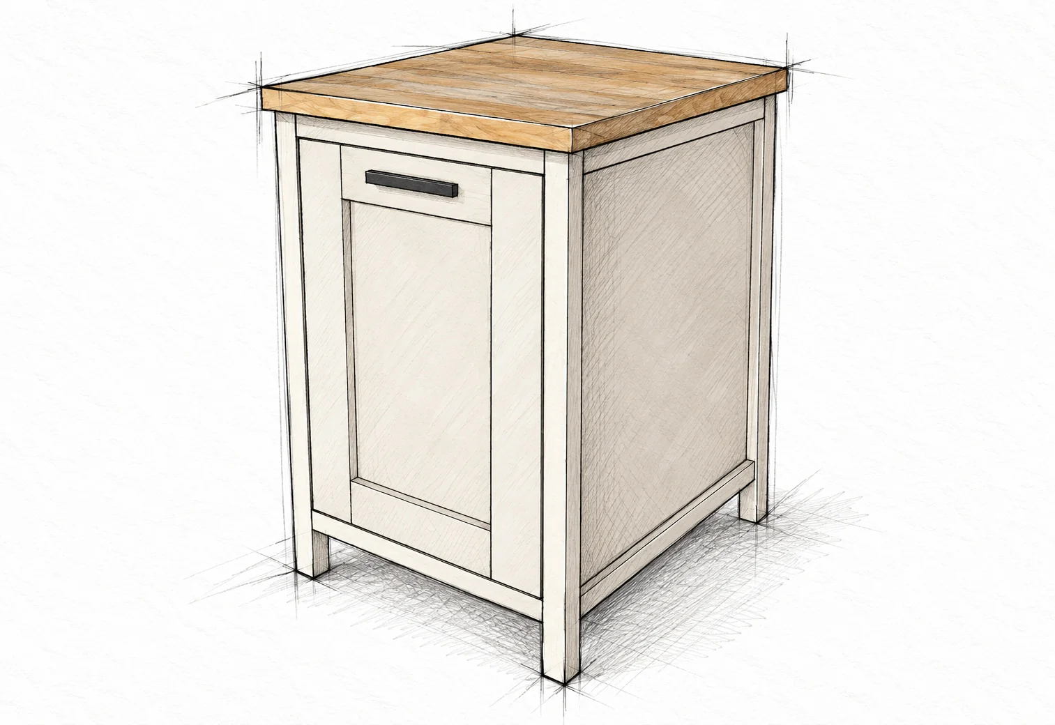
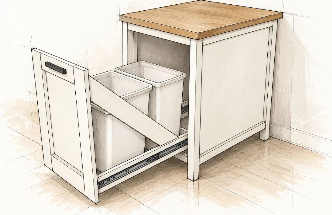
WOODWORKING PLANPullout Bin Kitchen Island
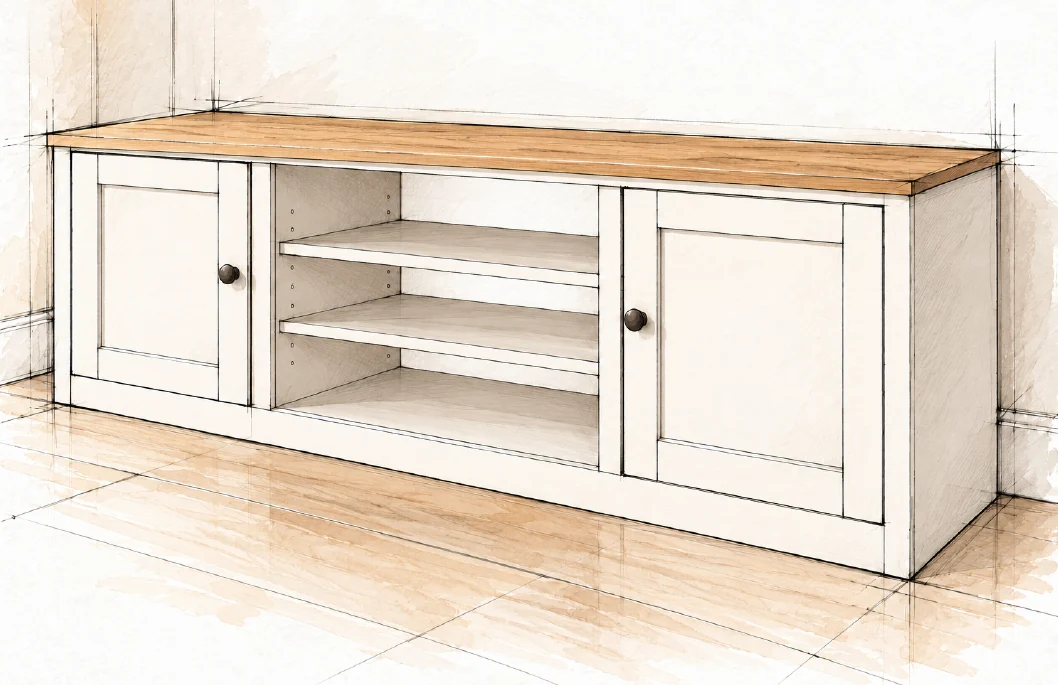
WOODWORKING PLANFarmhouse Media Console
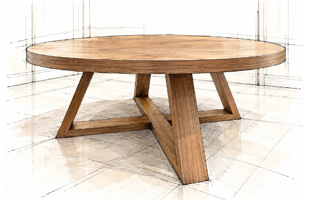
WOODWORKING PLANRound Coffee Table
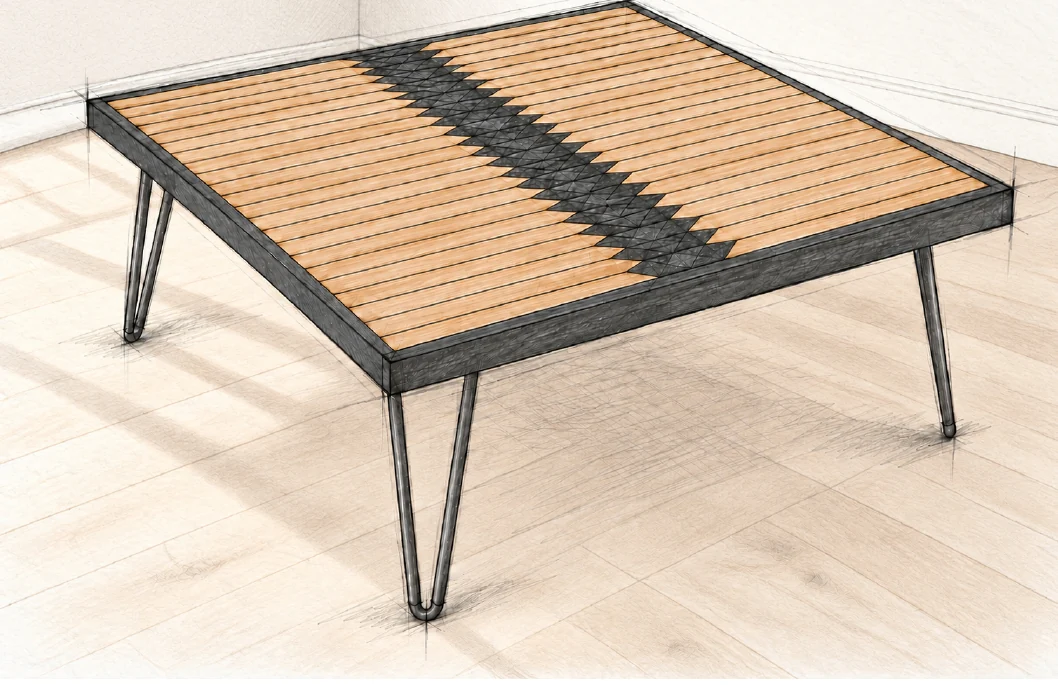
WOODWORKING PLANGeometric Hairpin Coffee Table
WOODWORKING PLANHollow Panel Waterfall Console
WOODWORKING PLANFarmhouse Console Table
WOODWORKING PLANBarn Door Console
WOODWORKING PLANBeginner Farm Table
WOODWORKING PLANFarmhouse Coffee Table
Pullout Bin Kitchen IslandFREE WOODWORKING PLAN
Storage / INTERMEDIATE

Pullout Bin Kitchen Island

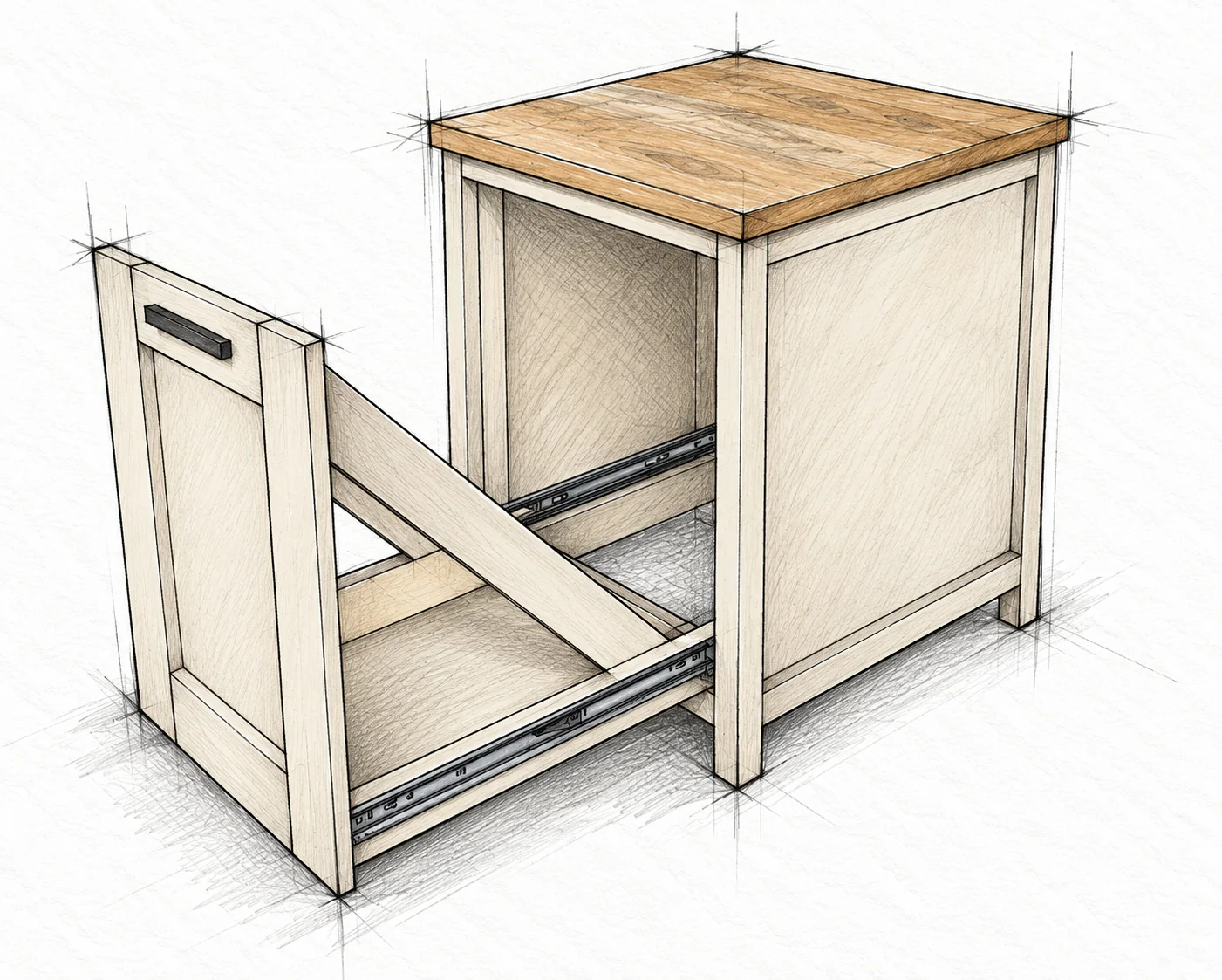
A compact paneled island with a braced pullout tray sized for two bins.

FINISHED DIMENSIONS22 1/2 × 27 1/4 in; 34 1/2 in plus top
SKILL LEVELIntermediate
WHAT IS INCLUDEDMaterials, cut list and illustrated steps
Read the free planMade this plan? Share your build
A GOOD BUILD STARTS WITH A CLEAR PLAN
  • Materials and tools
  • Cutting information and dimensions
  • Illustrated assembly steps
FROM THE FIRST CUT TO THE LAST DETAIL

Take it one step at a time

Everything you need to follow this build is written below. Read the materials, measurements and construction notes before your first cut.

Read the build steps

Yes. The complete plan is available to read on this page.
THE FREE BUILD GUIDE

Pullout Bin Kitchen Island

A compact paneled island with a braced pullout tray sized for two bins.

READ BEFORE BUYING

Plan the installation

A fitted cabinet project

This guide covers one indoor island with a single tall pullout drawer. Accurate squaring, slide alignment and measured-to-fit parts matter more than cutting everything at once. Read every step before buying lumber or hardware.

Choose the countertop first

Use a purchased laminate-faced wood-core countertop with a flat underside, supplied to the stated footprint. Its fabricator must approve the cabinet support and underside screw attachment in Step 13. Confirm the actual thickness, screw type, pilot holes and permitted penetration. Do not substitute stone, solid surface or rigidly fastened solid butcher block.

Match the bins and slides

Buy a matching pair of 24 in (609.6 mm) full-extension side-mount slides before cutting the drawer. Select the pair for the intended drawer and contents, and follow its mounting instructions. Check two actual bins together, including rims, handles, liners and clearance past the diagonal braces. Capacity labels alone do not prove fit.

Prevent tip-over

An extended loaded drawer can tip an unsecured cabinet. Before use, secure the cabinet with suitable anti-tip hardware installed to sound structure according to the hardware and substrate requirements. Plan this location before building; do not guess anchor types or load capacities.

ASSEMBLY REFERENCE

Know the finished form

One cabinet / One braced pullout drawer / One purchased top

pullout bin kitchen island — 3 illustration
Know the finished form · Pullout Bin Kitchen Island

Overall size

The cabinet body is 21-1/2 W × 26-1/4 D × 34-1/2 H in (546.1 × 666.8 × 876.3 mm). A centered 22-1/2 × 27-1/4 in (571.5 × 692.2 mm) top overhangs the body by 1/2 in (12.7 mm) on each side.

Height and clear space

Finished height is 34-1/2 in (876.3 mm) plus the actual top thickness. Leave space to open the drawer fully and lift out both bins. The drawing shows structure, not a load rating.

CHECK ACTUAL STOCK

Stock and fit dimensions

Dimension or checkInchesMillimetres
Nominal 2x2 actual section1-1/2 × 1-1/238.1 × 38.1
Nominal 1x2 actual section3/4 × 1-1/219.1 × 38.1
Nominal 1x4 actual section3/4 × 3-1/219.1 × 88.9
Plywood nominal thickness3/419.1
Front opening W × H18-1/2 × 27-1/2469.9 × 698.5
Drawer face frame W × H18-1/4 × 27-1/4463.6 × 692.2
Nominal face reveal all around1/83.2
Each bin maximum envelope W × H × DLess than 16 × 24 × 11Less than 406.4 × 609.6 × 279.4

Measure actual lumber and plywood before setting the jig. Inch dimensions control this build; millimetres are rounded conversions, not substitute nominal lumber sizes. Confirm the face-frame reveal on the assembled cabinet.

STOCK FOR ONE PROJECT

Materials and fasteners

Quantities are for one cabinet. Stock lengths allow the listed cuts and saw kerf; keep the drawer-width parts uncut until the slides are fitted.

QuantityItemSize or specification
2 boardsNominal 2x28 ft / 96 in (2438.4 mm) each; straight, dry stock
1 boardNominal 1x28 ft / 96 in (2438.4 mm)
1 boardNominal 1x24 ft / 48 in (1219.2 mm)
2 boardsNominal 1x410 ft / 120 in (3048.0 mm) each
1 sheetCabinet-grade plywood3/4 in nominal; 48 × 96 in (1219.2 × 2438.4 mm)
1 topPurchased laminate-faced wood-core countertop22-1/2 W × 27-1/4 D in (571.5 × 692.2 mm); fabricator-approved support and fastening
1 pairFull-extension side-mount slides24 in (609.6 mm); matched cabinet and drawer members, supplied or specified screws
2Removable waste binsVerify physical fit together; each below the envelope in the fit table
1Drawer pullMatching fasteners sized for the actual face assembly
STOCK FOR ONE PROJECT / CONTINUED

Materials and fasteners

QuantityItemSize or specification
1 boxPocket-hole screws1-1/4 in (31.8 mm); appropriate thread for the chosen wood and plywood
8Pocket-hole screws2-1/2 in (63.5 mm); front 2x2 rails to 2x2 legs
As neededBrad nails and face screws1-1/4 in (31.8 mm) brads; 1-1/4 in screws for face reinforcement
About 8Countertop cabinet screws2 in (50.8 mm) is the nominal starting length; actual fasteners must be approved for the selected top
As neededAdhesive and finishing suppliesWood glue, filler, abrasives, interior primer/paint or stain/clear finish
1 suitable setAnti-tip restraintSelect for cabinet, installation location and structural substrate; follow its instructions
WORKSHOP SETUP

Tools for the build

ToolPurpose or requirement
Tape, pencil and squareLabel parts, mark rail offsets, compare diagonals and confirm drawer geometry.
Level or straightedgeAlign both slide centerlines from the same base reference.
Miter sawSquare crosscuts and the two 45 degree brace ends. Support long stock.
Table saw or guided circular sawCut supported plywood accurately; use a suitable blade and safe sheet support.
Pocket-hole jig and drillJig settings for actual 3/4 and 1-1/2 in stock; matching drill, stop collar and driver.
Drill and pilot bitsSlide screws, drawer pull and top attachment; use a depth stop where needed.
Clamps and brad nailerHold joints aligned and fasten panels or face trim without shifting.
Sander and dust extractionSmooth edges and surfaces; prepare the chosen finish.
WORKSHOP SETUP

Safe workshop preparation

Protect yourself and support the work

Wear eye and hearing protection and suitable dust protection. Connect dust extraction where available. Keep loose clothing clear. Support sheet goods and long boards so neither the workpiece nor offcut can pinch the blade or fall.

Set up on scrap

Measure actual thickness, set the pocket-hole jig and stop collar, and test a joint in matching offcuts. For 3/4 in (19.1 mm) stock use the corresponding jig setup and 1-1/4 in (31.8 mm) pocket screws. For 1-1/2 in (38.1 mm) front rails use the matching setup and 2-1/2 in (63.5 mm) screws.

Clamp and fasten safely

Clamp mating parts flat with opposing pads bearing on opposite faces. Do not hold a small part in the fastener path. Keep fingers away from nail exits and use the nailer contact nose squarely at the intended entry point. Disconnect power or air before adjustments and jam clearing.

Prepare for finishing

Sand inaccessible surfaces before assembly, but keep glue contact areas bare. Remove dust without rounding fit edges. Apply coatings with ventilation and follow the product directions for drying, recoat times and disposal of oily rags.

CUT AND LABEL BEFORE ASSEMBLY

Cabinet cut list

All cuts are square unless stated otherwise. Panel dimensions are width × height. Label the inside and outside of both side assemblies before drilling.

PartQtyStock and useCut inCut mm
A42x2 legs34-1/2 long876.3 long
B41x2 side rails23-1/4 long590.6 long
C23/4 plywood Side panels23-1/4 × 30-1/2590.6 × 774.7
D22x2 front rails18-1/2 long469.9 long
E21x2 back rails18-1/2 long469.9 long
F13/4 plywood Back panel18-1/2 × 30-1/2469.9 × 774.7
CUT AND LABEL BEFORE ASSEMBLY

Drawer and top cut list

W is the measured clear distance between the fitted drawer sides, not a fixed 16 in (406.4 mm) cut. Keep H, I and K oversized until their steps.

PartQtyStock and useCut inCut mm
G21x4 drawer sides23-3/4 long603.3 long
H11x4 drawer backW; about 16W; about 406.4
I13/4 plywood Structural frontW × 25-1/2W × 647.7
J21x4 diagonal braces31 long point to long point787.4 long point to long point
K13/4 plywood Drawer bottomFit opening; about 16 × 22-1/4Fit opening; about 406.4 × 565.2
L21x4 face stiles27-1/4 long692.2 long
M21x4 face rails11-1/4 long285.8 long
N1Purchased top Width × depth22-1/2 × 27-1/4571.5 × 692.2
CUT AND LABEL BEFORE ASSEMBLY / CONTINUED

Drawer and top cut list

Brace cuts

Cut both ends of each J brace at 45 degrees. The end cuts are not parallel. Measure 31 in (787.4 mm) between the two long points, then dry-fit both braces before fastening.

Buy the top to finished size

The countertop is a purchased component, not a laminated-lumber build in this guide. The fabricator must confirm the footprint, flat support contact and suitable underside fasteners before installation.

MAKE THE STOCK GO FURTHER

Lay out before cutting

Plan for saw kerf

The examples below allow a 1/8 in (3.2 mm) saw kerf per cut. Your actual blade, damaged ends and knots may require more stock. Draw the layout first and cut on the waste side of the line.

2x2 and 1x2 boards

From each 96 in (2438.4 mm) 2x2 cut two 34-1/2 in (876.3 mm) legs and one 18-1/2 in (469.9 mm) rail. Cut all four 23-1/4 in (590.6 mm) side rails from the 96 in 1x2; cut both 18-1/2 in back rails from the 48 in (1219.2 mm) 1x2.

1x4 boards

One 120 in (3048.0 mm) board can provide both 31 in (787.4 mm) braces, one 27-1/4 in (692.2 mm) stile and one 23-3/4 in (603.3 mm) side. The other provides the remaining stile and side, both 11-1/4 in (285.8 mm) rails, and the measured drawer back.

Plywood layout

Place the two side panels side by side in the first 30-1/2 in (774.7 mm) length of the sheet. Below them, place the back panel beside the oversized drawer-front blank. Reserve the remaining area for the measured drawer bottom. Leave kerf between every part; do not pre-cut the fitted widths.

STEP 01 / CABINET AND DRAWER ASSEMBLY

Build the side frames

A × 4 / B × 4 / 1-1/4 in pocket screws

pullout bin kitchen island — 13 illustration
Build the side frames · Pullout Bin Kitchen Island

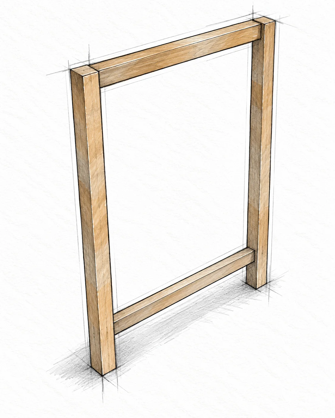
Set the rails

For each side, place two legs A on a flat surface. Fit two rails B between them, flush with the outside/back plane of the legs. Set the upper rail flush with the leg tops; set the lower rail bottom 4 in (101.6 mm) above the feet.

Join and square

Drill two 3/4 in (19.1 mm) pocket holes at each rail end. Clamp the joints and drive 1-1/4 in (31.8 mm) pocket screws. Compare diagonal measurements before tightening. Make two matching side frames.

STEP 02 / CABINET AND DRAWER ASSEMBLY

Close both side panels

C × 2 / Wood glue / 1-1/4 in brads and pocket screws

pullout bin kitchen island — 14 illustration
Close both side panels · Pullout Bin Kitchen Island

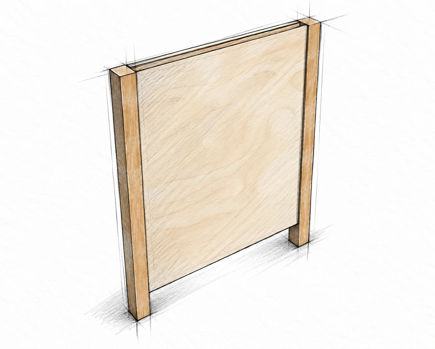
Prepare each panel

Dry-fit C between the legs over the inside faces of the rails. Its top is flush with the leg tops and its lower edge is 4 in (101.6 mm) above the feet. Drill 3/4 in (19.1 mm) pockets along both vertical edges, about every 8 in (203.2 mm).

Fasten the panel

Apply glue where the panel contacts the upper and lower rails. Fix it to those rails with 1-1/4 in (31.8 mm) brads, then drive 1-1/4 in pocket screws into the legs. Repeat for the second side, keeping both assemblies square.

STEP 03 / CABINET AND DRAWER ASSEMBLY

Connect the two sides

D × 2 / E × 2 / Two pocket screws at every rail end

pullout bin kitchen island — 15 illustration
Connect the two sides · Pullout Bin Kitchen Island

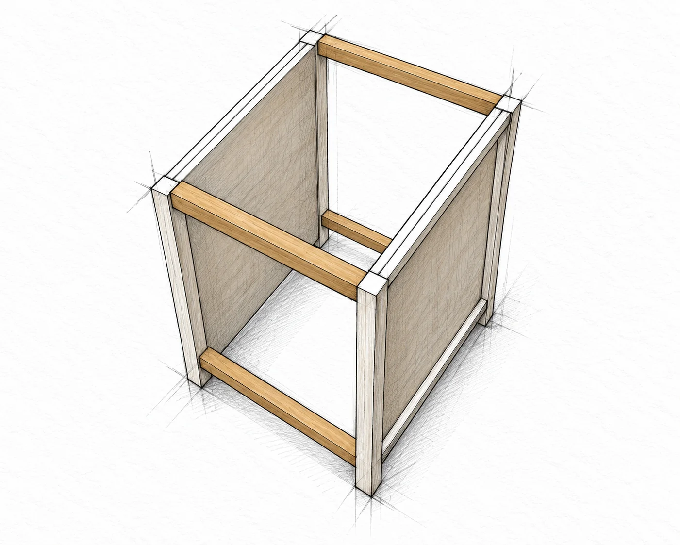
Join the back

Fit the 1x2 rails E between the rear legs, flush to the outside back plane. Use the 3/4 in (19.1 mm) jig setting and 1-1/4 in (31.8 mm) pocket screws. Keep the upper rail flush at the top and the lower rail bottom 4 in (101.6 mm) above the feet.

Join the front

Use the 1-1/2 in (38.1 mm) jig setting for square 2x2 rails D. Attach them to the front legs with 2-1/2 in (63.5 mm) pocket screws, matching the upper and lower elevations. Keep the body square and untwisted.

STEP 04 / CABINET AND DRAWER ASSEMBLY

Install the back panel

F × 1 / Wood glue / 1-1/4 in brads and pocket screws

pullout bin kitchen island — 16 illustration
Install the back panel · Pullout Bin Kitchen Island

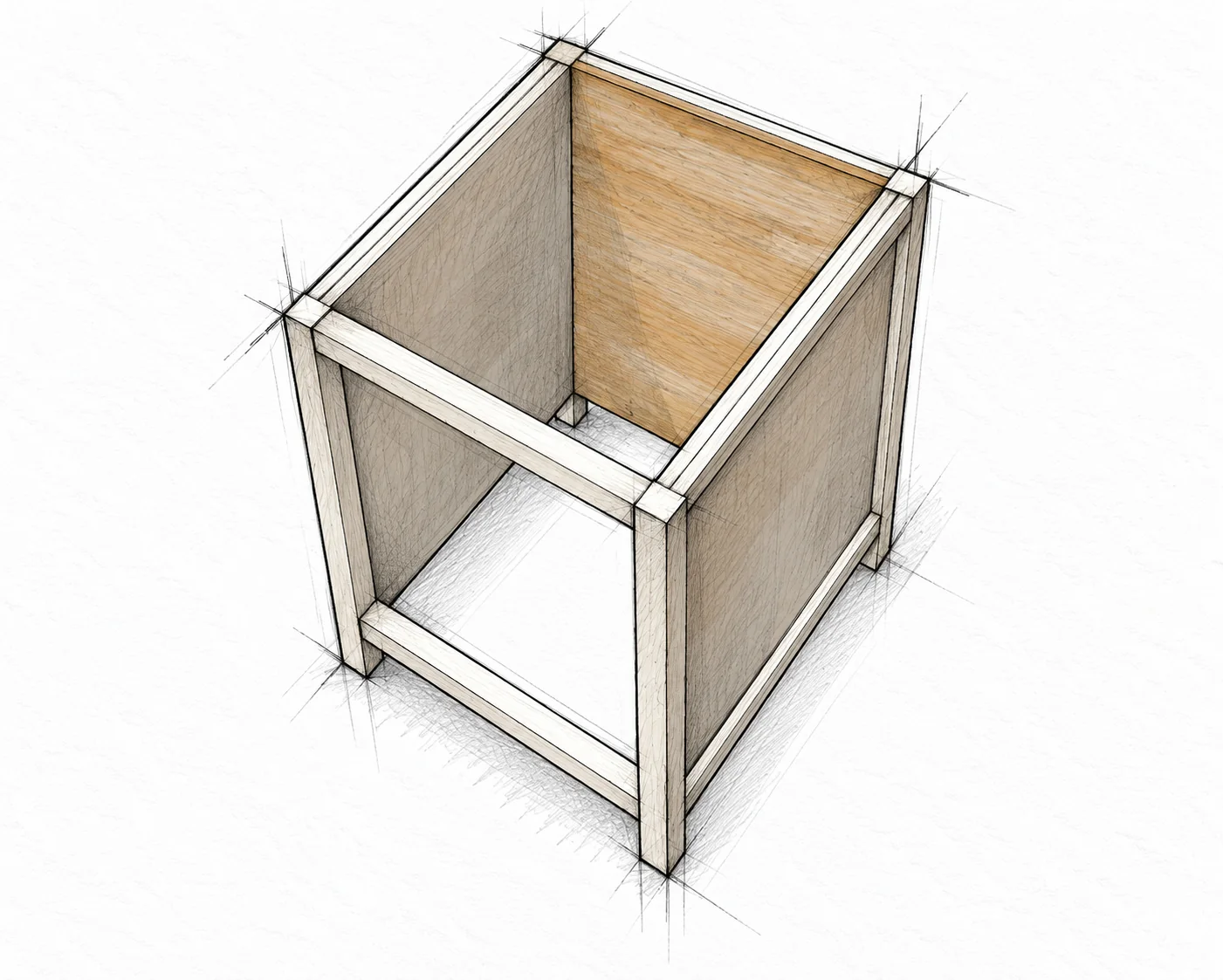
Fit before fastening

Place the back panel F between the rear legs, against the inside faces of E. Its top aligns with the leg tops and its lower edge aligns with the side panels. Check diagonal measurements across the cabinet opening.

Close the carcass

Use the same panel method as the sides: 3/4 in (19.1 mm) pockets along the vertical edges and 1-1/4 in (31.8 mm) pocket screws into the legs. Glue and brad the panel to the back rails. Let the glue cure without disturbing the square body.

STEP 05 / CABINET AND DRAWER ASSEMBLY

Set the cabinet slides

24 in full-extension slide pair / Manufacturer-specified screws

pullout bin kitchen island — 17 illustration
Set the cabinet slides · Pullout Bin Kitchen Island

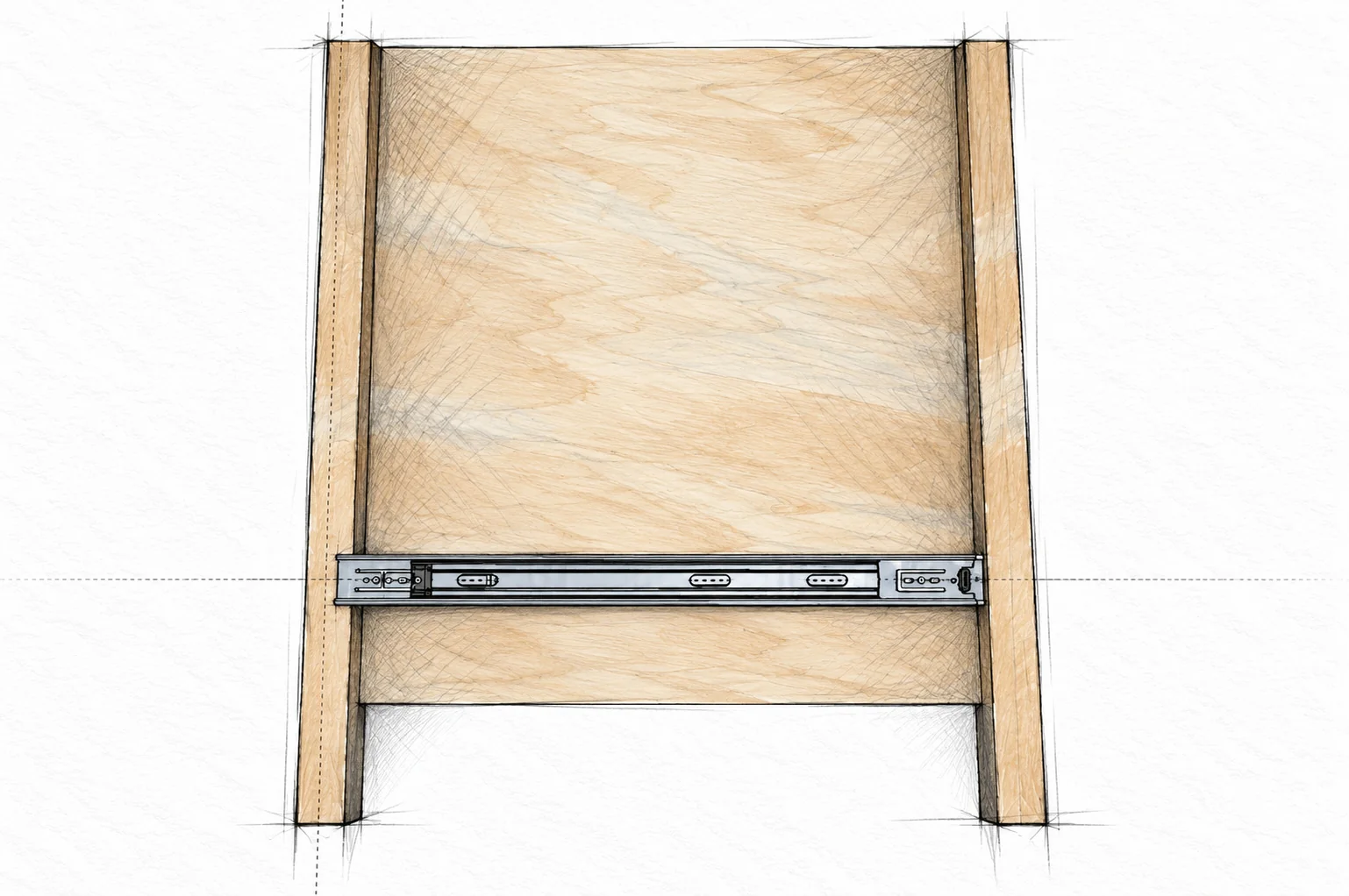
Mark from the base

On both inside side panels, mark a level horizontal line 8-1/2 in (215.9 mm) above the bottoms of the legs. Use the same datum on both sides. The drawing isolates one inner side for clarity.

Position the cabinet members

Separate each slide as instructed by its maker. Center its mounting holes on the line and set its front end 3/4 in (19.1 mm) behind the front edge of the leg. Fit both slides parallel, using the specified screws and all required mounting points. Check that screw tips cannot emerge outside.

STEP 06 / CABINET AND DRAWER ASSEMBLY

Fit the drawer members

G × 2 / Matching left and right drawer-slide members

pullout bin kitchen island — 18 illustration
Fit the drawer members · Pullout Bin Kitchen Island

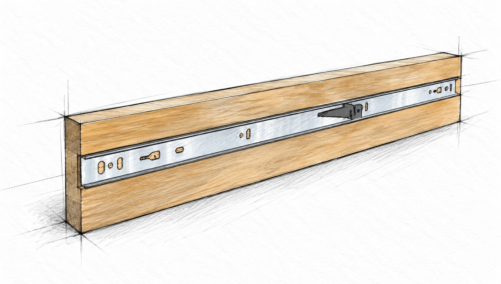
Mark the board faces

On the outside face of each G side, mark a line 1-1/2 in (38.1 mm) below the upper edge. Keep the pair mirrored so the slide hardware faces outward when installed.

Attach the hardware

Position each drawer member with its front end flush to the front end of the side board and its mounting-hole centerline on the mark. Follow the slide maker's hole and screw instructions. Keep both members straight and at identical heights.

STEP 07 / CABINET AND DRAWER ASSEMBLY

Measure the fitted width

Installed drawer sides G / Measure W at front and rear

pullout bin kitchen island — 19 illustration
Measure the fitted width · Pullout Bin Kitchen Island

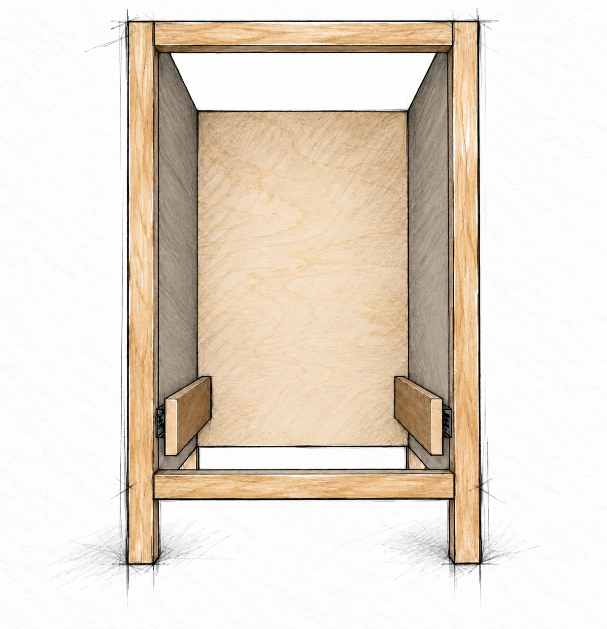
Engage both sides

Insert each drawer side into its matching cabinet member without twisting the hardware. Move the sides together through the same travel and check that both slides engage correctly.

Record the real opening

Measure the clear distance between the inside faces of G at front and rear. This is W, approximately 16 in (406.4 mm). The measurements should agree. Correct cabinet squareness or slide alignment before cutting H and I; do not force a fixed-width box between misaligned slides.

STEP 08 / CABINET AND DRAWER ASSEMBLY

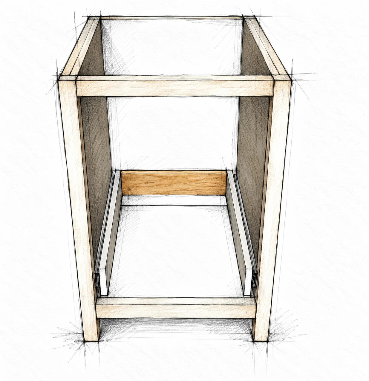
Join the drawer back

H cut to measured W / 1-1/4 in pocket screws

pullout bin kitchen island — 20 illustration
Join the drawer back · Pullout Bin Kitchen Island

Cut the fitted crosspiece

Cut H to the measured W from Step 7. Fit it between the drawer sides at their rear ends, with upper and lower edges aligned to G. It must not spread the slides or pull them inward.

Fasten and check travel

Drill 3/4 in (19.1 mm) pockets at both ends of H and attach it with 1-1/4 in (31.8 mm) pocket screws. Support the assembly while working. Check that the drawer still moves freely before adding the tall front.

STEP 09 / CABINET AND DRAWER ASSEMBLY

Add the tall drawer front

I cut to W × 25-1/2 in / 1-1/4 in fasteners

pullout bin kitchen island — 21 illustration
Add the tall drawer front · Pullout Bin Kitchen Island

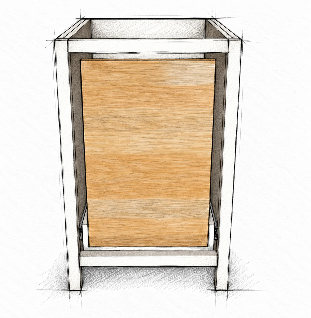
Fit the structural panel

Cut I to W wide and 25-1/2 in (647.7 mm) high. Set it between the drawer sides at the front, with its lower edge aligned with the bottom edges of G. Keep the panel upright and square to both sides.

Secure the lower corners

Use the 3/4 in (19.1 mm) pocket-hole setup and 1-1/4 in (31.8 mm) pocket screws at the lower side connections. Glue and 1-1/4 in brads hold the contacting edges as needed. Keep any visible face area free of pocket holes; the decorative frame will not hide the entire panel.

STEP 10 / CABINET AND DRAWER ASSEMBLY

Brace the tall front

J × 2 / Wood glue / 1-1/4 in pocket screws and brads

pullout bin kitchen island — 22 illustration
Brace the tall front · Pullout Bin Kitchen Island

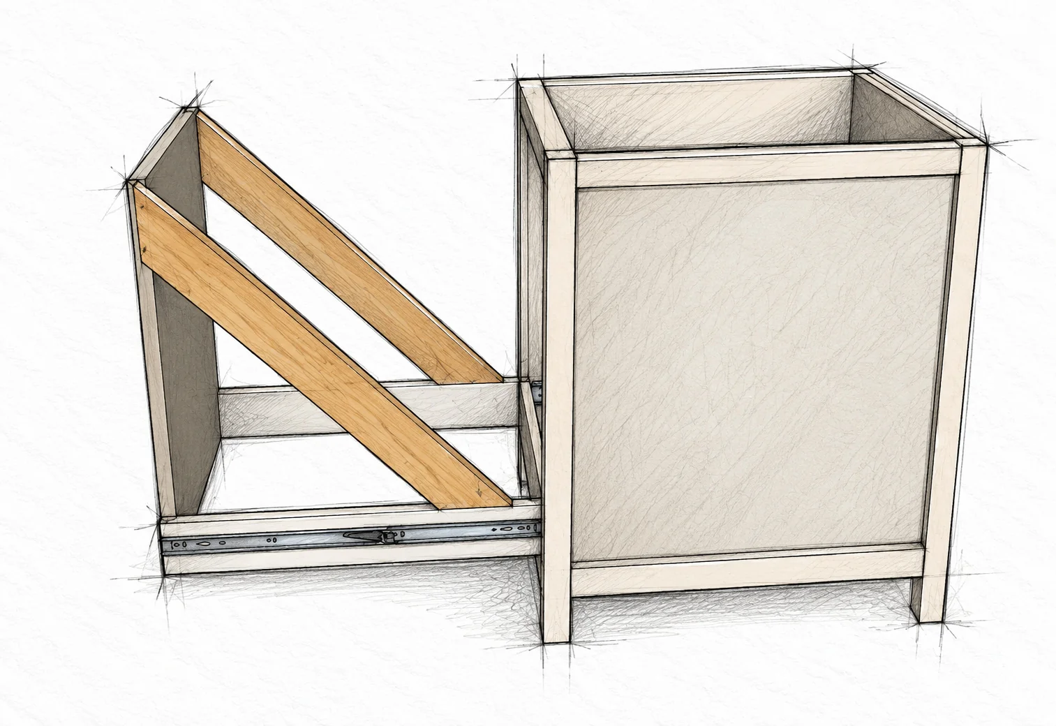
Dry-fit both braces

Fit one diagonal J on each side of the drawer. Each brace runs from the upper inside of the tall front down to the rear end of a low side board. The 45 degree end faces must seat flat. Keep the two braces parallel; they do not form an X.

Fix without racking

With the drawer supported and square, glue the contacting faces. Use 3/4 in (19.1 mm) pockets and 1-1/4 in (31.8 mm) pocket screws at the lower side connections; secure the upper front contacts with glue and 1-1/4 in brads. Keep fasteners clear of slides and visible face areas.

STEP 11 / CABINET AND DRAWER ASSEMBLY

Fit the drawer bottom

K cut to the actual inside opening / 1-1/4 in pocket screws

pullout bin kitchen island — 23 illustration
Fit the drawer bottom · Pullout Bin Kitchen Island

Measure the assembled tray

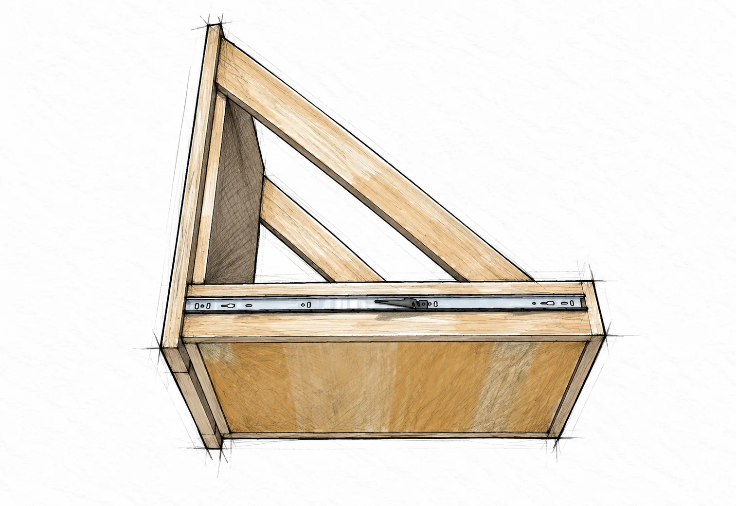
Release the drawer as directed by the slide maker and support it safely. Measure the inside opening between its sides, front and back. K is approximately 16 × 22-1/4 in (406.4 × 565.2 mm), but cut it to your actual opening.

Attach from underneath

Drill 3/4 in (19.1 mm) pockets around all four edges of K on the underside. Fit the panel inside the surrounding members at their lower edges, then fasten with 1-1/4 in (31.8 mm) pocket screws. The illustration shows the underside. Confirm square and clear slide hardware.

STEP 12 / CABINET AND DRAWER ASSEMBLY

Frame the drawer face

L × 2 / M × 2 / 1-1/4 in pocket screws, brads and face screws

pullout bin kitchen island — 24 illustration
Frame the drawer face · Pullout Bin Kitchen Island

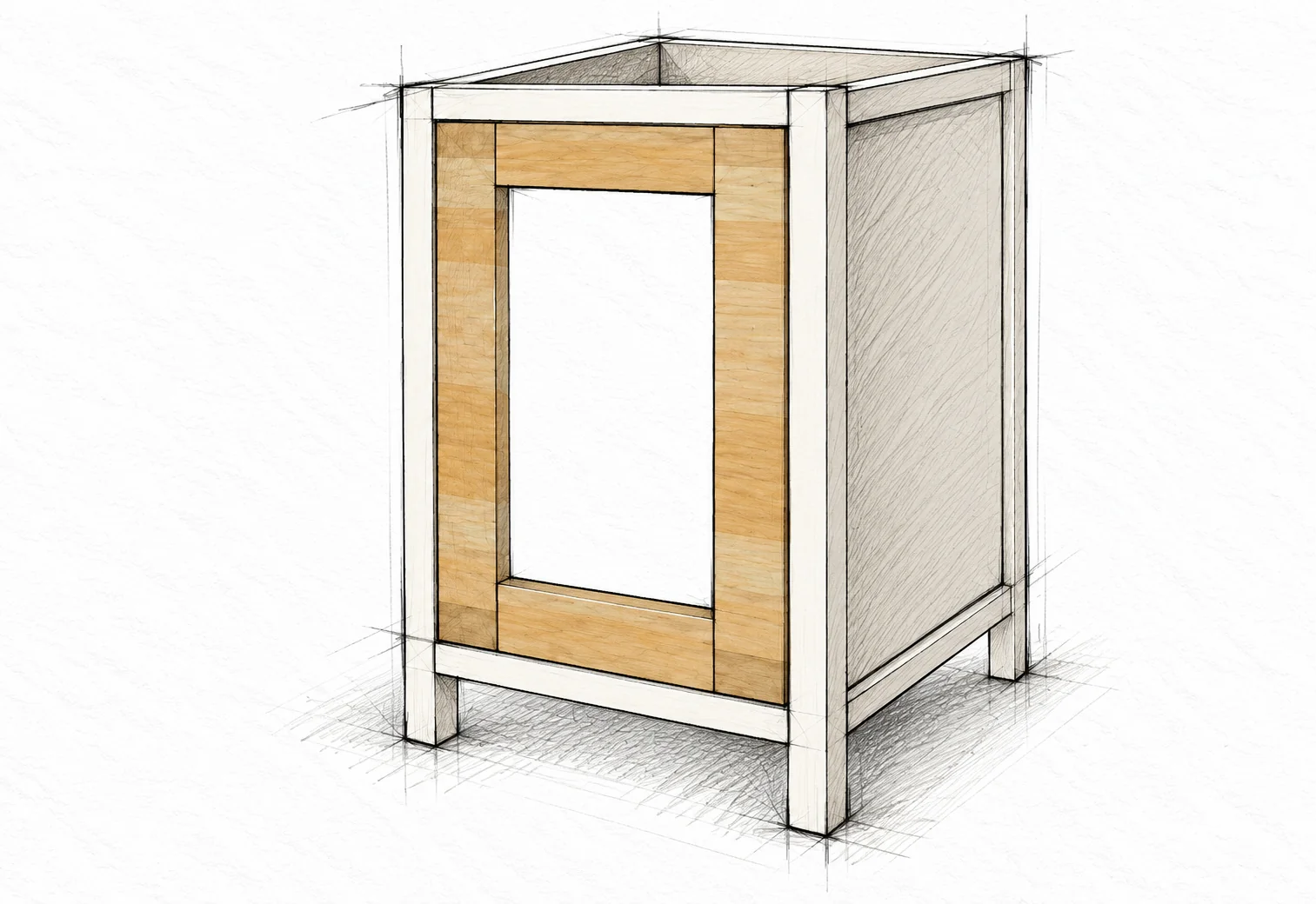
Assemble the face frame

Join the two rails M between the full-height stiles L with 3/4 in (19.1 mm) pockets and 1-1/4 in (31.8 mm) pocket screws. The outer frame is 18-1/4 W × 27-1/4 H in (463.6 × 692.2 mm). The drawing isolates this frame; the structural panel remains behind it.

Align and reinforce

With the drawer closed, center the frame for an even reveal, nominally 1/8 in (3.2 mm) all around. Attach to I with glue and 1-1/4 in brads. Open the drawer and reinforce from inside with 1-1/4 in screws. Verify screw depth and keep the pull location clear.

STEP 13 / CABINET AND DRAWER ASSEMBLY

Attach the selected top

N × 1 / Approved underside fasteners / Drawer pull

pullout bin kitchen island — 25 illustration
Attach the selected top · Pullout Bin Kitchen Island

Center and verify

Center the purchased top for a 1/2 in (12.7 mm) overhang on each side. Confirm level, full support contact and fabricator approval for this cabinet. Total height is 34-1/2 in (876.3 mm) plus the measured top thickness.

Fasten from below

Drive the approved cabinet screws upward through the upper side rails into the top. About eight 2 in (50.8 mm) screws are a planning allowance, not a universal specification. Verify length, pilot depth and engagement before drilling; no point may approach the finished surface. Install the pull using its template and correct fasteners.

COUNTERTOP ATTACHMENT CHECK

Check the screw path

Confirm the actual support stack

The upper side rail is 1-1/2 in (38.1 mm) tall in the vertical screw path. With no recess or additional layer, a 2 in (50.8 mm) screw projects nominally 1/2 in (12.7 mm) beyond that rail. This is only a geometric check, not proof that the selected top accepts that engagement.

Get the top-specific requirements

Use only a wood-core laminate top whose fabricator permits this underside fastening and support arrangement. The fabricator's instructions govern screw type, engagement, pilot diameter and depth, spacing and any required movement clearance. Measure the actual rail and top; include any specified washers or countersink when checking the effective penetration.

Stop if the details do not agree

If the approved screws cannot grip sufficiently without risking the surface, or the top needs a different support or attachment system, do not improvise or use longer screws blindly. Obtain a compatible top specification before proceeding. This guide does not provide a solid-wood movement attachment detail.

FINISH AND INSPECT

Finish and inspect

Prepare and finish the cabinet

Remove the drawer and protect or remove hardware before coating. For paint, fill exposed holes, let filler dry, sand smooth, remove dust and apply compatible primer and durable interior paint. For stain, test on scrap first, stain evenly, then use a suitable clear finish; color-match exposed filler after staining if needed.

Keep fit surfaces clear

Apply light, even coats and follow all drying and curing directions. Do not coat slide mechanisms, glue faces or the purchased laminate surface. Avoid finish buildup at the drawer reveal. Seal exposed plywood edges against routine kitchen moisture, and wipe spills promptly.

Restrain and test before loading

Install the selected anti-tip restraint to suitable structure before testing a loaded drawer. Start empty: cycle the drawer slowly, inspect every fastener, and confirm smooth travel and clearances. Fit both bins with their liners and check access and removal. Stop if the cabinet rocks, lifts, racks or binds.

Use within the hardware limits

No load rating is established for this assembly. Follow the slide and restraint requirements, keep loads modest and inspect joints regularly. Do not sit, stand or lean on the open drawer. Use a cutting board and trivets on the countertop; clean and maintain it as its maker directs.

MAKE IT YOURS

Measure your own stock and dry-fit before fastening. If you make this project, I would love to see what you built.

Share your build