WOODWORKING · DIY · A HANDMADE HOME @grainbyjoy
GRAIN by JoyWOODWORKING PLANS · WORKSHOP STORIES · HOME
FIND YOUR NEXT GOOD THING
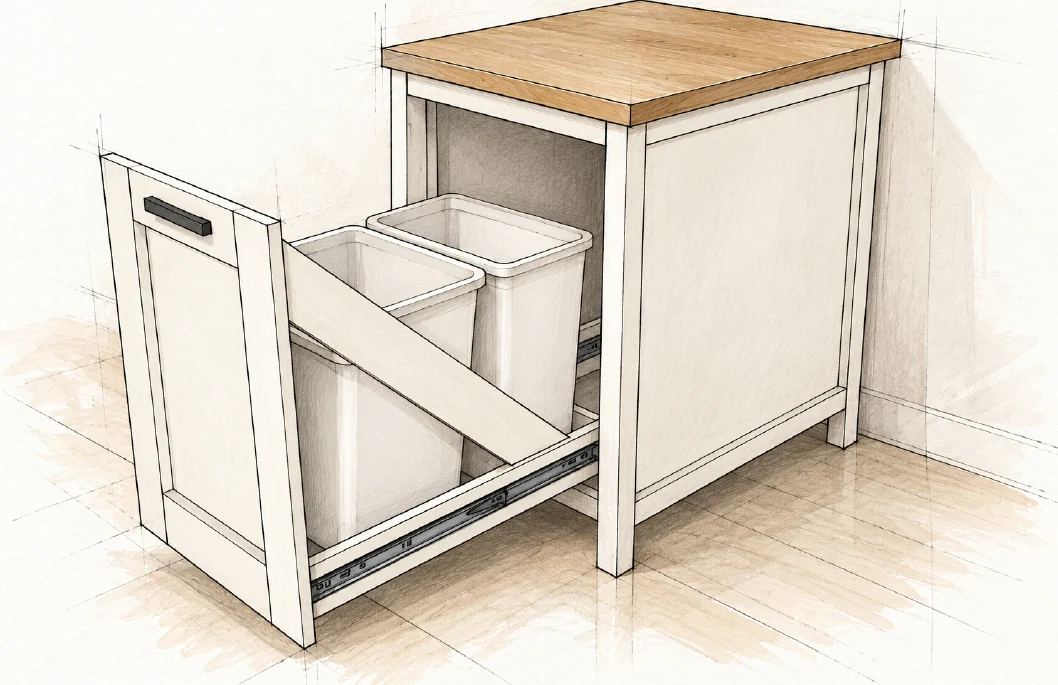
WOODWORKING PLANPullout Bin Kitchen Island
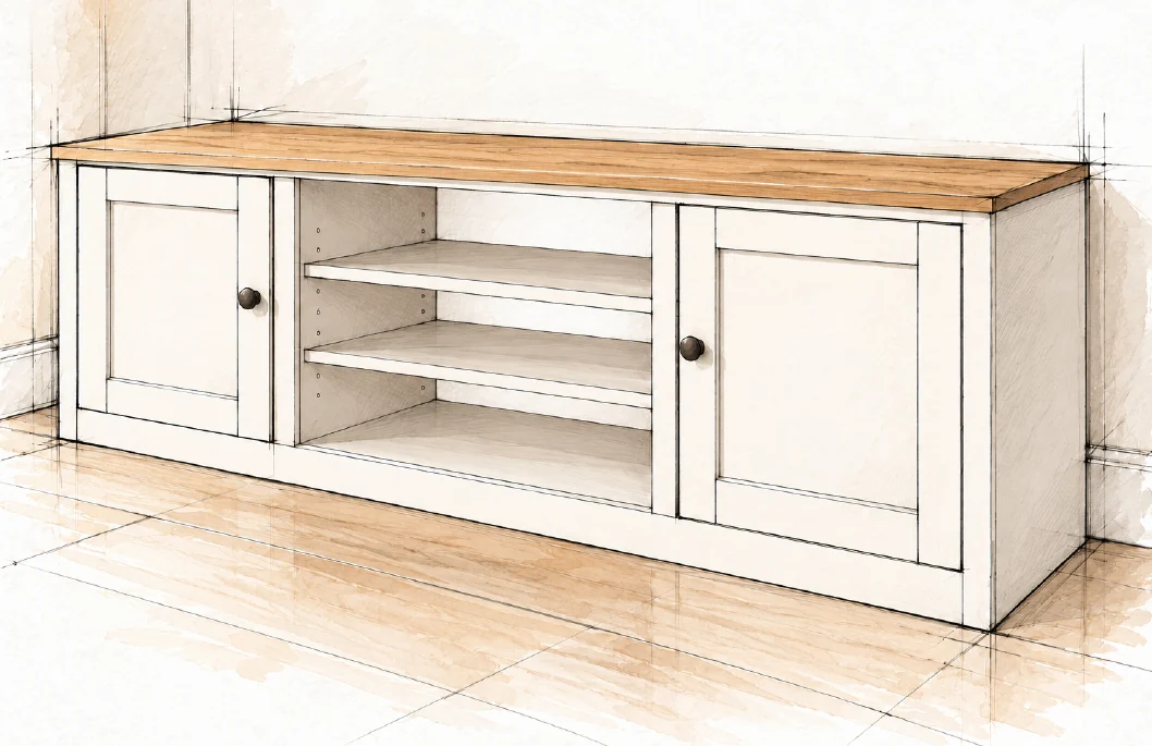
WOODWORKING PLANFarmhouse Media Console
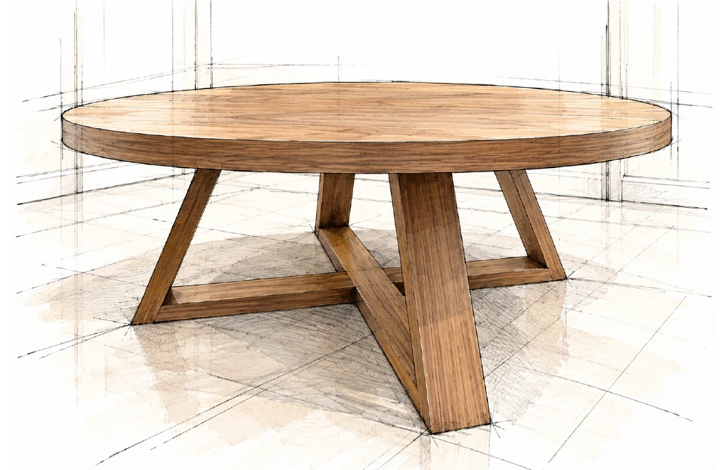
WOODWORKING PLANRound Coffee Table
WOODWORKING PLANGeometric Hairpin Coffee Table
WOODWORKING PLANHollow Panel Waterfall Console
WOODWORKING PLANFarmhouse Console Table
WOODWORKING PLANBarn Door Console
WOODWORKING PLANBeginner Farm Table
WOODWORKING PLANFarmhouse Coffee Table
FREE WOODWORKING PLAN
Storage / INTERMEDIATE

Table Height Pantry Cabinet

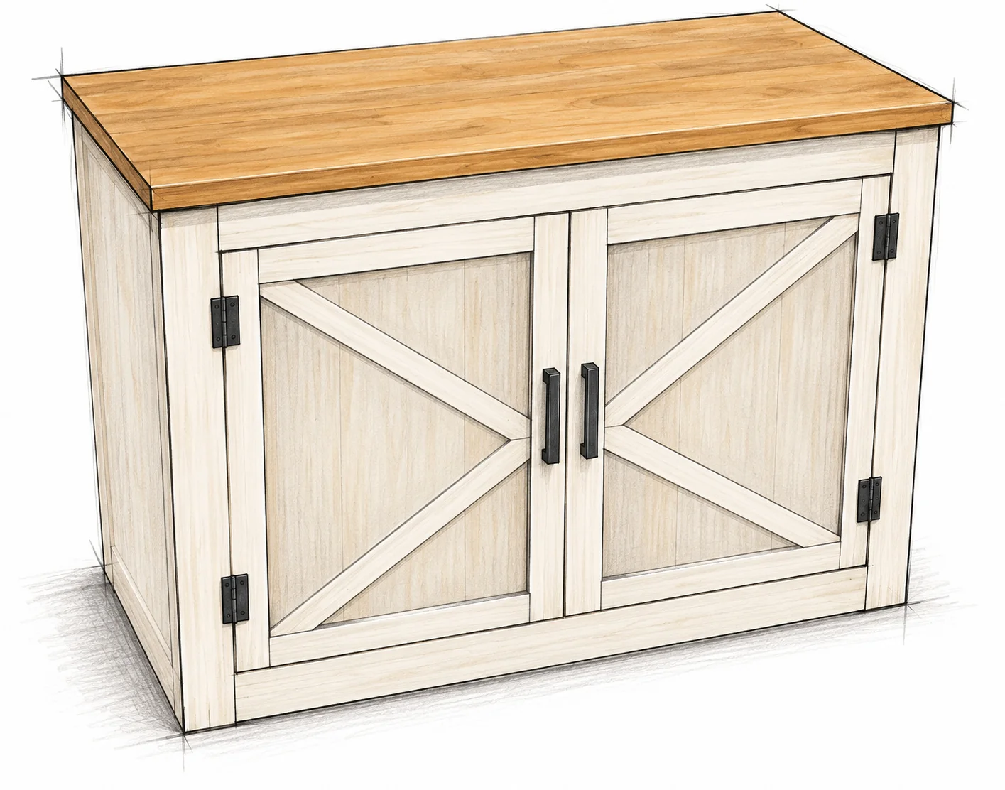
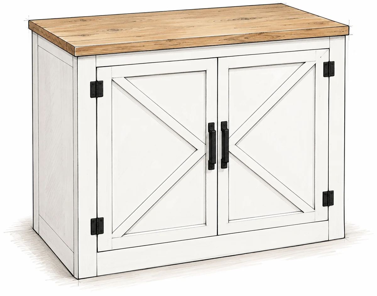
A low storage cabinet with a timber top and paired chevron doors.

FINISHED DIMENSIONS35 1/2 × 16 1/4 × 30 3/4 in
SKILL LEVELIntermediate
WHAT IS INCLUDEDMaterials, cut list and illustrated steps
Read the free planMade this plan? Share your build
A GOOD BUILD STARTS WITH A CLEAR PLAN
  • Materials and tools
  • Cutting information and dimensions
  • Illustrated assembly steps
FROM THE FIRST CUT TO THE LAST DETAIL

Take it one step at a time

Everything you need to follow this build is written below. Read the materials, measurements and construction notes before your first cut.

Read the build steps

Yes. The complete plan is available to read on this page.
THE FREE BUILD GUIDE

Table Height Pantry Cabinet

A low storage cabinet with a timber top and paired chevron doors.

READ BEFORE YOU BUILD

The cabinet at a glance

This guide builds one low cabinet only. It does not include tall side cabinets or a larger pantry installation.

FeatureInchesMillimeters
Overall top width35 1/2901.7
Overall top depth16 1/4412.8
Overall height30 3/4781.1
Cabinet side height30762.0
Open face frame area30 1/2 × 24774.7 × 609.6
Each shelf width × depth16 5/8 × 12422.3 × 304.8

How it is assembled

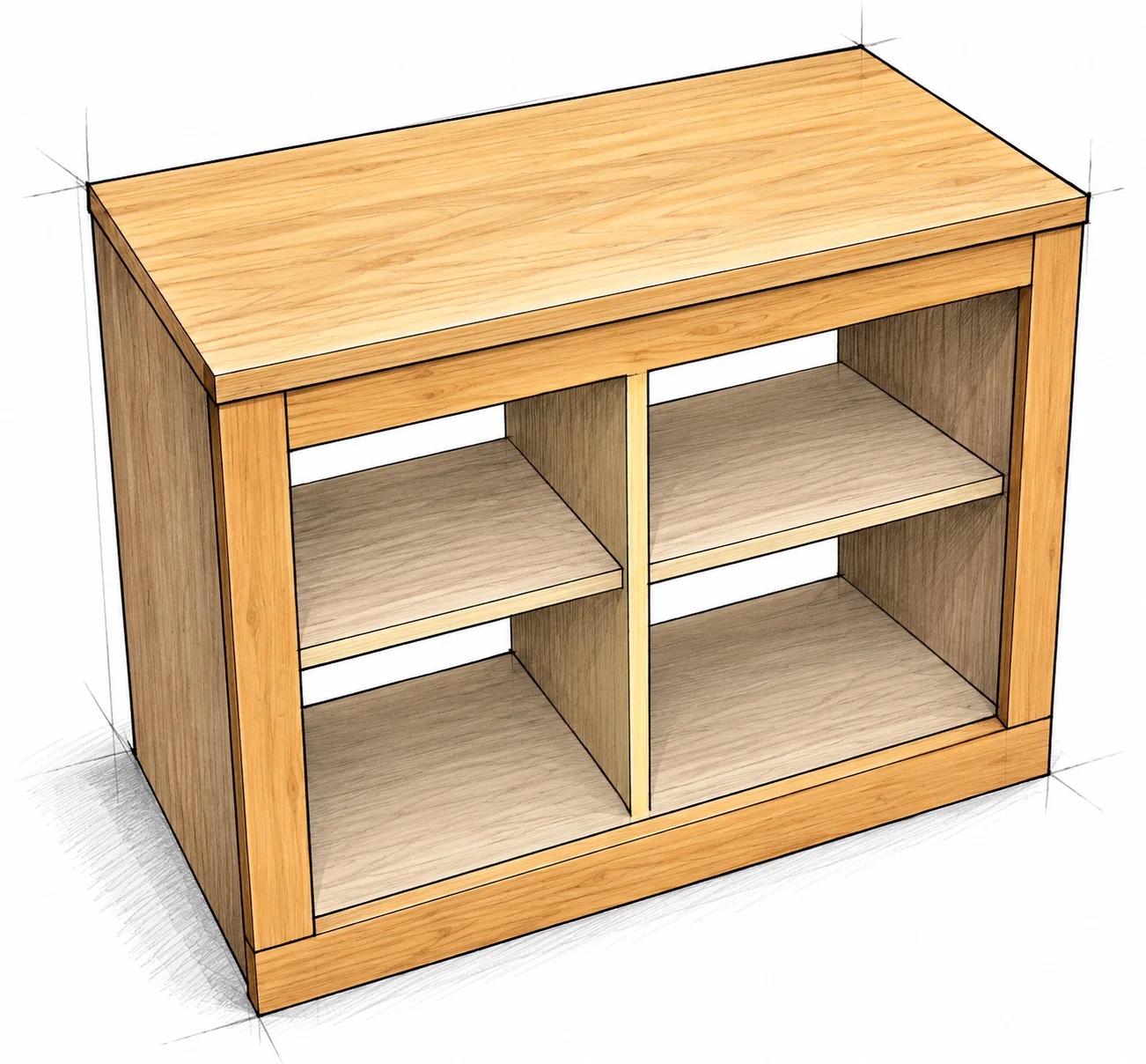
A plywood body carries the center divider and two fixed shelves. A four-piece face frame covers the front edges. The back braces the cabinet square, and two inset doors share a large X-shaped detail.

Choose the hardware before cutting doors

Select four surface-mounted hinges suitable for inset doors and the actual door build-up, plus two pulls. Confirm the required clearances and screw lengths. Hole locations and mounting details depend on that hardware.

SHOPPING LIST / WOOD

Buy the stock

Select straight, dry boards and flat panels. The sizes below include a practical stock format; final part sizes are in the cut lists.

QuantityStockSize or requirement
1 sheet3/4 in hardwood plywood 19.1 mm nominal4 × 8 ft / 48 × 96 in 1219.2 × 2438.4 mm
1 panel1/2 in hardwood plywood 12.7 mm nominalAt least 24 × 48 in 609.6 × 1219.2 mm For the doors only
1 panel1/4 in hardwood plywood 6.4 mm nominalEnough for a 35 × 27 3/4 in 889.0 × 704.9 mm back
1 panel3/4 in edge-glued timber 19.1 mm nominalEnough for a 35 1/2 × 16 1/4 in 901.7 × 412.8 mm top
1 boardNominal 1×38 ft / 96 in long 2438.4 mm
1 boardNominal 1×44 ft / 48 in long 1219.2 mm

Also buy 1/4 in (6.4 mm) craft-board trim. The exact strip requirements are on page 8; choose enough sound length and width for all strips, their saw kerfs and fitting waste.

SHOPPING LIST / JOINERY

Fasteners and supplies

Buy compatible fasteners for the actual wood and tools. Quantities of screws and brads are not fixed by this plan; allow enough for all shown joints and test pieces.

ItemSpecificationUsed for
Pocket-hole screws1 1/4 in / 31.8 mmCabinet, divider, frame, shelves and top
Brad nails or staples1 in / 25.4 mmBack panel
Brad nails1/2 in / 12.7 mmDoor perimeter trim
Brad nails3/4 in / 19.1 mmDoor diagonal trim
4 hingesSurface-mounted; match inset-door fitTwo hinges per door; use specified screws
2 pullsChoose before drillingOne per door; use specified screws
Wood glueInterior wood adhesiveStructural and trim joints

Finishing and installation supplies

Have abrasives, compatible filler if desired, paint or stain, and a suitable protective finish ready. Assess the location for an appropriate anti-tip restraint and wall fixings before placing the cabinet in service.

WORKSHOP SETUP

Tools and safe preparation

Read the whole sequence and your tool manuals before starting. Plan a supported cutting area and a flat assembly surface.

Measure and mark

Use a tape measure, pencil, square and straightedge. Have clamps long enough to hold the cabinet and face frame, plus small clamps for door trim. Label every part before drilling.

Cut the panels and narrow trim

Use a suitable saw with a guide for sheet goods, and a crosscut saw for boards. Use a safe ripping setup for the narrow craft-board strips. Keep guards in place and use push sticks or other approved work-holding aids; keep hands away from the blade.

Drill and fasten

Use a drill/driver, a pocket-hole jig with its matched stepped bit, stop collar and driver, suitable pilot bits, and a brad nailer. A compatible stapler is an option for the back only. Follow each tool’s pressure and fastener limits.

Protect yourself

Wear eye and hearing protection. Use dust extraction and suitable dust protection. Clamp and fully support panels before cutting. Disconnect power or air before adjustments or clearing jams. Never place a hand behind a nail’s path.

Prepare to finish

Use sanding tools and dust-removal equipment. Follow finish instructions for ventilation, protective equipment, drying and curing. Handle oily rags exactly as the finish maker directs to reduce fire risk.

CUT LIST / MAIN PANELS

Cabinet and door panels

Dimensions are finished sizes, not cutting diagrams. Length × depth or width is shown as appropriate. Label parts A to G.

Part and quantityThick inCut size inCut size mm
A Side panels × 23/430 × 15762.0 × 381.0
B Base × 13/434 × 15863.6 × 381.0
C Divider × 13/426 1/2 × 12673.1 × 304.8
D Shelves × 23/416 5/8 × 12422.3 × 304.8
E Timber top × 13/435 1/2 × 16 1/4901.7 × 412.8
F Back × 11/435 × 27 3/4889.0 × 704.9
G Door blanks × 21/223 3/4 × 15 1/16603.3 × 382.6

Measure real thickness

Nominal panel thicknesses of 3/4, 1/2 and 1/4 in convert to 19.1, 12.7 and 6.4 mm. Actual plywood may be thinner. Check fit on the dry assembly before committing to shelves, frame and door cuts.

CUT LIST / FACE FRAME

Four solid timber pieces

The side stiles sit on the wide bottom rail. The top rail fits between the stiles. All ends are square cuts.

PartQtyNominal stockLength inLength mm
H Side stile21×326 1/2673.1
I Top rail11×330 1/2774.7
J Bottom rail11×435 1/2901.7

Nominal and actual sizes

A nominal 1×3 is typically 3/4 × 2 1/2 in (19.1 × 63.5 mm). A nominal 1×4 is typically 3/4 × 3 1/2 in (19.1 × 88.9 mm). Confirm your stock before cutting: these actual face widths determine the door opening.

Use the boards efficiently

The two stiles and top rail total 83 1/2 in (2120.9 mm), before kerf and end trimming, from the 96 in (2438.4 mm) 1×3. The bottom rail uses 35 1/2 in (901.7 mm) from the 48 in (1219.2 mm) 1×4.

Check the finished frame

Overall frame size is 35 1/2 × 30 in (901.7 × 762.0 mm). The opening is 30 1/2 × 24 in (774.7 × 609.6 mm). Compare both diagonals; equal lengths indicate a square rectangle.

CUT LIST / DOOR TRIM

Trim for two doors

Use flat 1/4 in (6.4 mm) craft boards. Rip the perimeter strips to 1 1/2 in (38.1 mm) wide and the diagonals to 3/4 in (19.1 mm) wide.

PartQtyWidth inLength inLength mm
K Vertical trim41 1/223 3/4603.3
L Horizontal trim41 1/212 1/16306.4
M Diagonal trim43/4Scribe to fitScribe to fit

Buy enough usable trim

The four vertical strips need 95 in (2413.0 mm) total length at 1 1/2 in (38.1 mm) wide. The four horizontals need 48 1/4 in (1225.6 mm) at that same width. Add saw kerfs and end trimming, plus four separate diagonal lengths at 3/4 in (19.1 mm) wide.

Do not rely on a bundle count

Check each board’s sound width and length. A 96 in (2438.4 mm) strip leaves only 1 in (25.4 mm) beyond the four verticals, before kerfs and end trimming. Buy extra stock if needed.

Cut the diagonals after the border

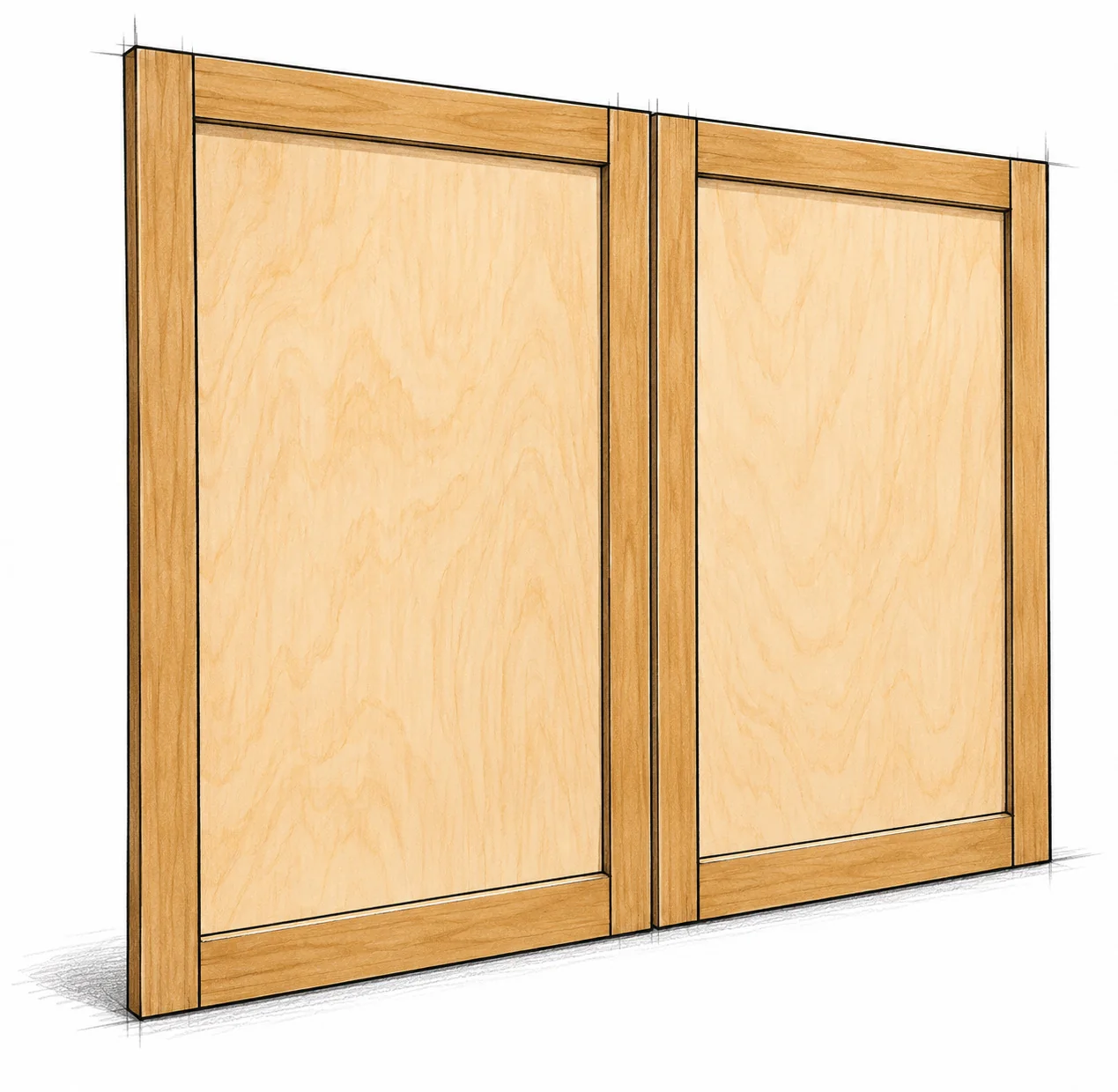
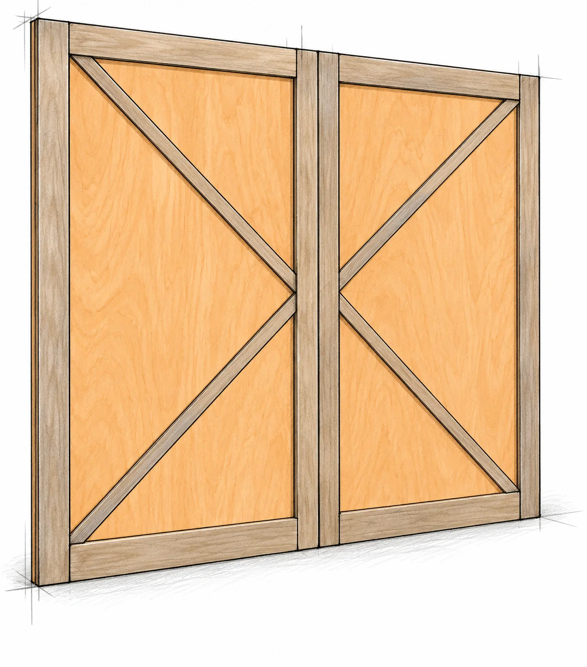
The two door borders must be fitted first. Lay diagonal strips over the actual openings, mark the end angles and trim to fit. The pair forms one large X: a right-pointing chevron on the left door and a left-pointing chevron on the right.

ACCURACY BEFORE ASSEMBLY

Cutting and joinery setup

Use the written inch dimensions; sketches are not full-size templates. Millimeter values are rounded to 0.1 mm. Do not combine rounded values to set out a joint.

Plan the sheet cuts

One 15 in (381.0 mm) wide strip can provide both 30 in (762.0 mm) sides and the 34 in (863.6 mm) base: 94 in (2387.6 mm) total before kerf. A separate 12 in (304.8 mm) strip supplies the divider and shelves. Keep the 1/2 in (12.7 mm) door stock separate.

Cut on the waste side

Square a reference edge, mark the finished dimension and leave the blade on the waste side. Allow for kerf and end trimming. Compare matching sides and doors before drilling. Test-fit shelves to the actual cabinet bays.

Set the pocket-hole jig

For stages 1 to 6, set the jig and drill collar for the actual 3/4 in (19.1 mm nominal) material, following the jig maker’s instructions. Use 1 1/4 in (31.8 mm) pocket screws. The 3/4 in setting is material thickness, not the depth of a straight hole.

Test, clamp and control the driver

Make a scrap joint first. Mark pocket faces for driver access, clamp each joint flush, then drive until snug without stripping. Test the brads on offcuts of the actual layers, especially the 3/4 in (19.1 mm) diagonal brads; no point may emerge from a door back.

STEP 01 / ASSEMBLY

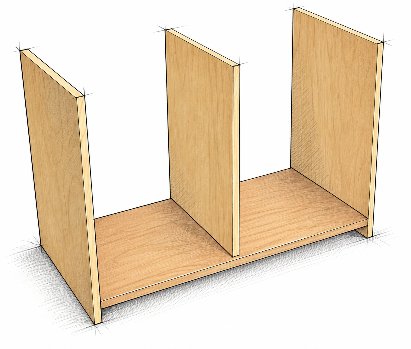
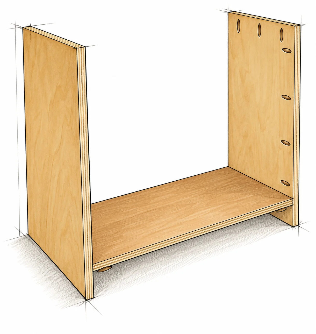
Build the cabinet body

A × 2 / B × 1

Build the cabinet body · Table Height Pantry Cabinet

Prepare the pocket holes

Drill pocket holes in both ends of base B to join the sides. Prepare the sides’ front and top edges, and the base’s front edge, for the frame and top. Keep the holes on accessible inner faces; follow the jig’s spacing guidance.

Position and fasten the base

Mark a line 2 3/4 in (69.9 mm) above the bottom of each side for the base underside. Dry-clamp B between A with front and back edges aligned. Glue and fasten through B with 1 1/4 in (31.8 mm) pocket screws.

Check the body

Keep both sides square to the base and parallel. With 3/4 in stock, the base top is 3 1/2 in (88.9 mm) above the feet and the outside width is 35 1/2 in (901.7 mm).

STEP 02 / ASSEMBLY

Add the center divider

C × 1 / Completed body

Add the center divider · Table Height Pantry Cabinet

Mark the center

Use the 26 1/2 × 12 in (673.1 × 304.8 mm) divider. Drill pocket holes at its top and bottom for the later top and the base. Center it across the base width and position it squarely on the base as shown.

Glue and secure

Dry-clamp and check both bays. Glue the divider-to-base joint and drive 1 1/4 in (31.8 mm) pocket screws through the bottom pockets. Leave the upper pockets accessible for the top panel.

Check the bays

Each clear bay is 16 5/8 in (422.3 mm) wide when the divider is 3/4 in (19.1 mm) thick. The divider top must align with both side tops.

STEP 03 / ASSEMBLY

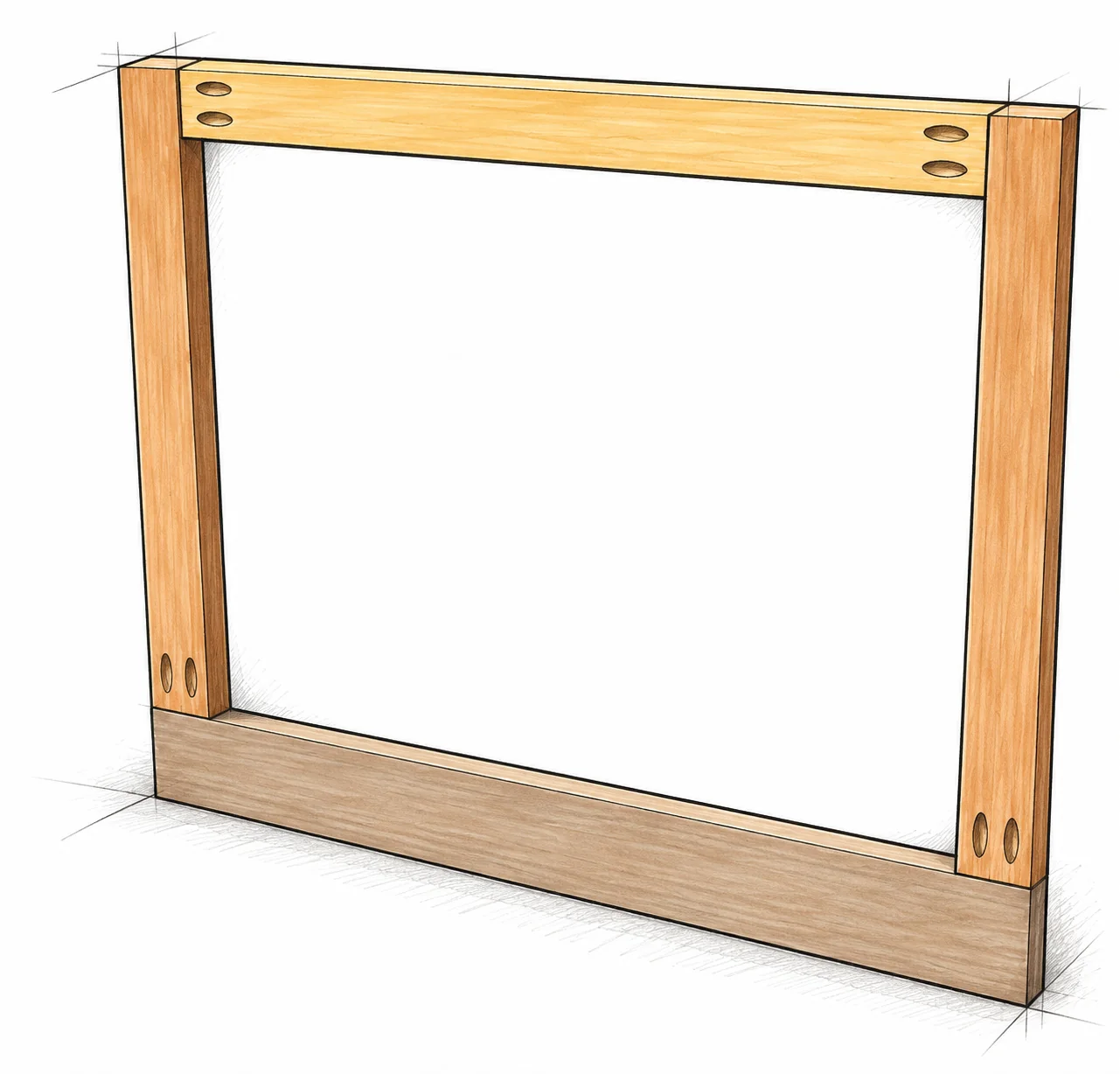
Make the face frame

H × 2 / I × 1 / J × 1

Make the face frame · Table Height Pantry Cabinet

Lay out the rectangle

Place the two 1×3 stiles on the full-width 1×4 bottom rail. Fit the 1×3 top rail between the stiles, flush to their tops. Put pocket holes on the back: at both top-rail ends and at the bottom end of each stile.

Clamp and assemble

Dry-fit on a flat surface. Glue all four joints, clamp the faces flush and drive 1 1/4 in (31.8 mm) pocket screws. Keep the frame flat as the screws tighten.

Check before the glue sets

The outside is 35 1/2 × 30 in (901.7 × 762.0 mm). Compare diagonal measurements and check all four corners. Set the frame aside until after the shelves are installed.

STEP 04 / ASSEMBLY

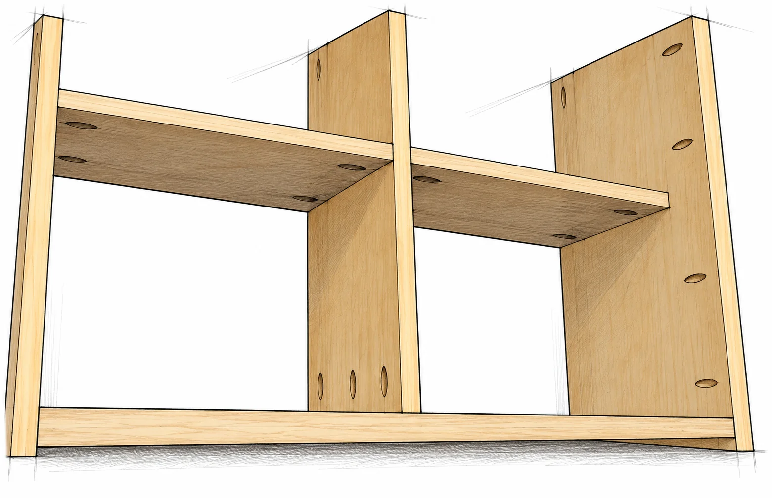
Install the two shelves

D × 2 / Cabinet body

Install the two shelves · Table Height Pantry Cabinet

Set the shelf height

Dry-fit one 16 5/8 × 12 in (422.3 × 304.8 mm) shelf in each bay. The illustrated layout places the shelf underside 13 in (330.2 mm) above the base top. You may choose another height to suit storage; mark both sides of each bay.

Glue and fasten

Drill pocket holes in each shelf end, facing down. Align the shelf depth with the divider. Clamp level and glue each end to the side or divider. Drive 1 1/4 in (31.8 mm) pocket screws while keeping the shelves at the marks.

Check access and alignment

Both shelves must be level and firmly joined at both ends. Keep the front clear for the inset doors and retain access to the body pockets needed for the face frame.

STEP 05 / ASSEMBLY

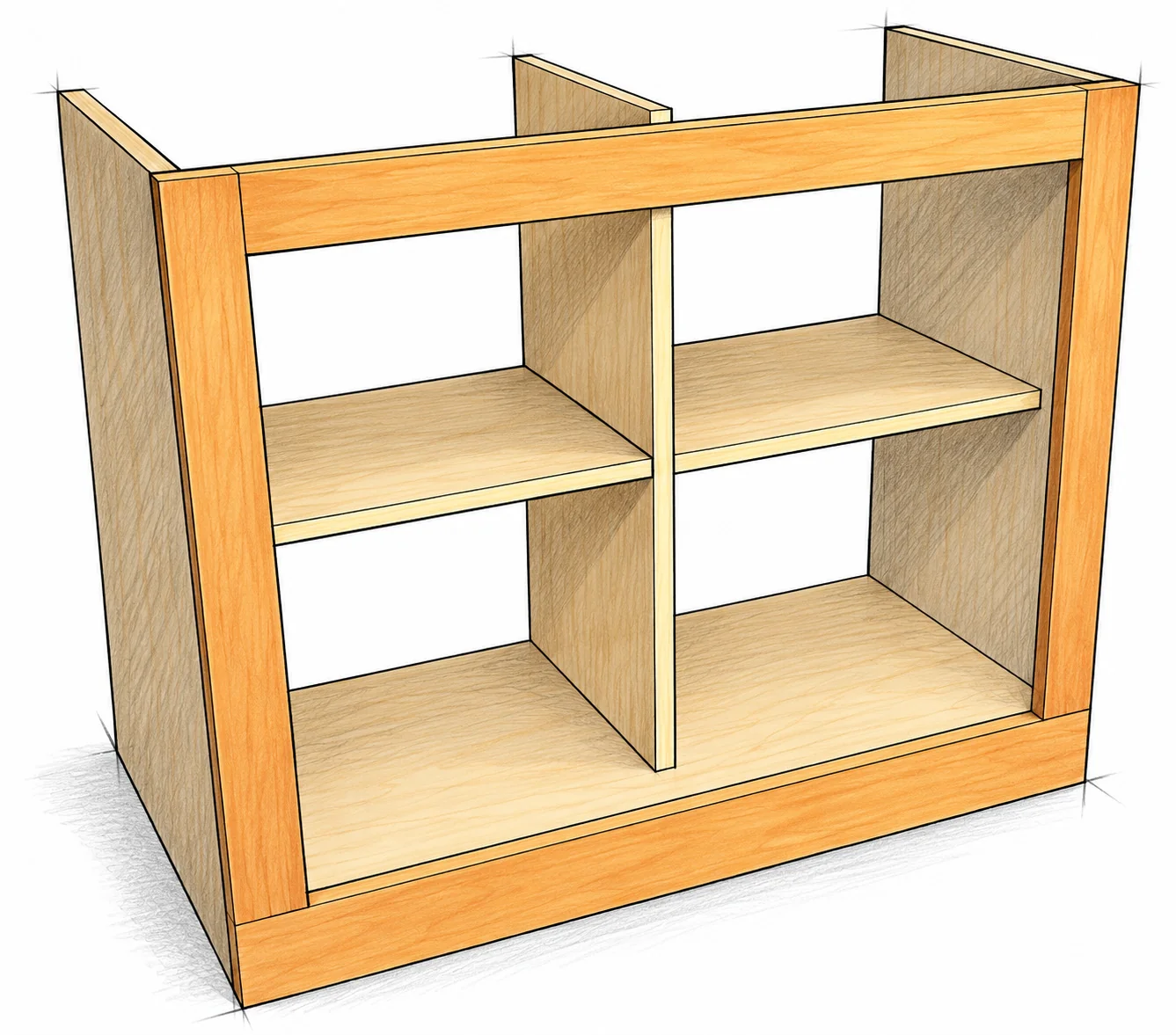
Attach the face frame

Completed body / Completed frame

Attach the face frame · Table Height Pantry Cabinet

Dry-fit the frame

Set the frame against the cabinet front. Align its outside edges with the side panels, its top with the side tops, and its bottom with the side feet. The wide bottom rail conceals the raised base edge.

Glue and fasten from inside

Apply glue to the mating front edges. Clamp the frame flush and square. Use 1 1/4 in (31.8 mm) pocket screws through the prepared cabinet pockets into the back of the frame. Keep screw paths clear of nearby frame joints.

Check the door opening

The target opening is 30 1/2 × 24 in (774.7 × 609.6 mm). Measure the actual opening at several points; the frame must not twist or bow. Remove glue squeeze-out before it hardens.

STEP 06 / ASSEMBLY

Fit the timber top

E × 1 / Cabinet with frame

Fit the timber top · Table Height Pantry Cabinet

Size and position the top

Cut the 3/4 in (19.1 mm) edge-glued panel to 35 1/2 × 16 1/4 in (901.7 × 412.8 mm). Dry-fit it on the cabinet. Its width matches the cabinet, so align the side edges; verify front and rear placement before fixing.

Secure from inside

Apply glue at the mating supports, clamp the top and drive 1 1/4 in (31.8 mm) pocket screws upward through the prepared side and divider holes. Keep the top seated and check that screw tips cannot break through.

Finish planning

The top can be stained before assembly. Keep glue contact areas bare and follow the finish’s cure instructions. Overall height is 30 3/4 in (781.1 mm) with a true 3/4 in thick top.

STEP 07 / ASSEMBLY

Attach the back panel

F × 1 / Rear view

Attach the back panel · Table Height Pantry Cabinet

Square the cabinet first

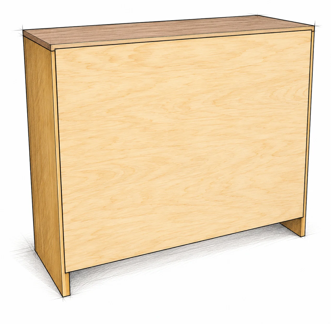
Lay or support the cabinet securely with the rear accessible. Compare the cabinet’s diagonals and adjust until square. Dry-fit the 35 × 27 3/4 in (889.0 × 704.9 mm) back over the rear opening, centered side-to-side.

Fasten into solid edges

Hold the back in place and attach with 1 in (25.4 mm) brads or compatible staples. Mark the supporting panel edges so every fastener enters wood rather than empty space. Keep hands out of the fastening path.

Check the result

Keep the cabinet square while working around the back. Inspect the interior and edges for protruding fasteners. The back must sit flat and must not rack the cabinet out of square.

STEP 08 / ASSEMBLY

Cut and fit the door blanks

G × 2 / Use 1/2 in plywood

Cut and fit the door blanks · Table Height Pantry Cabinet

Cut a matching pair

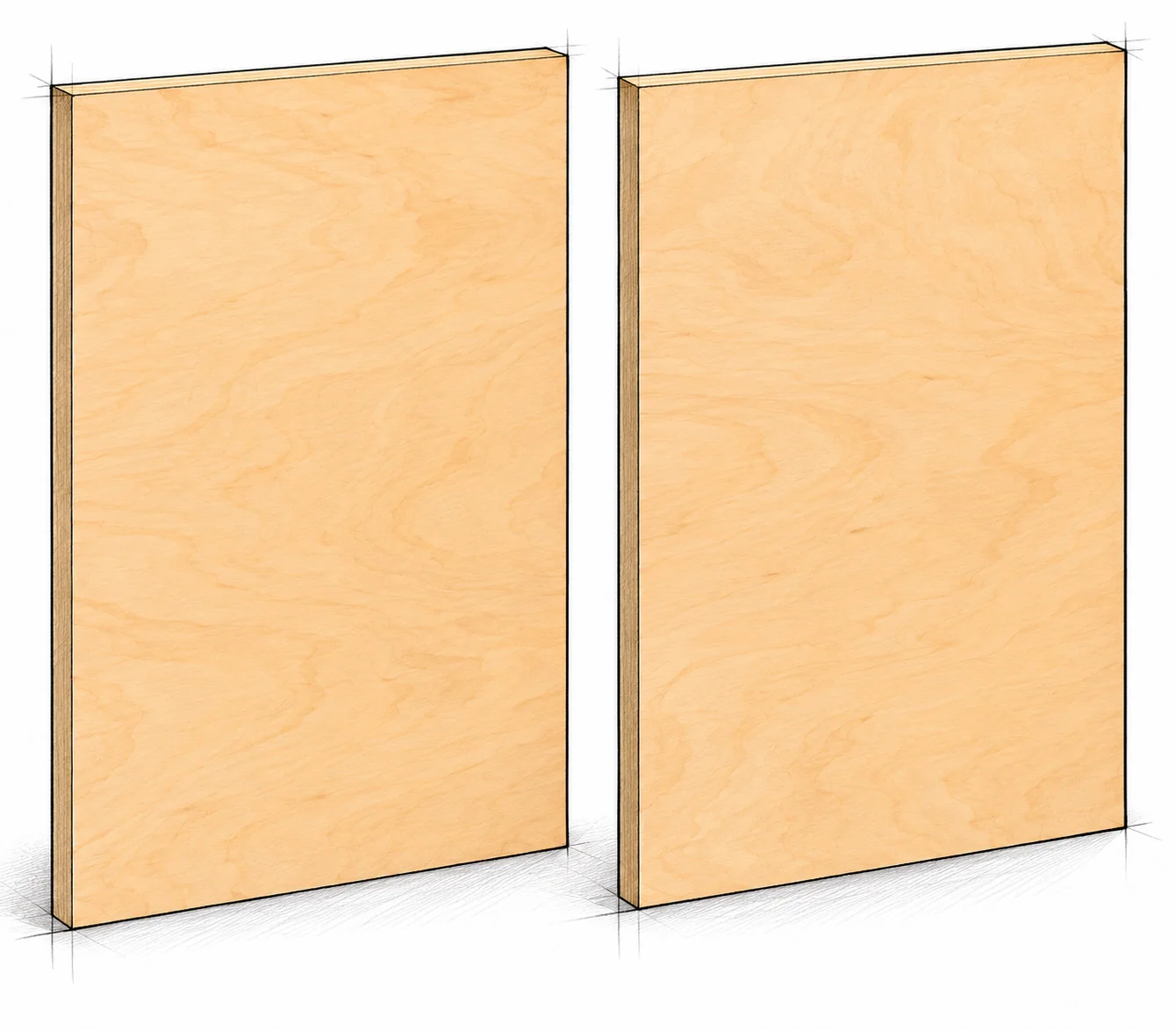
Cut two 1/2 in (12.7 mm) plywood panels, each 23 3/4 × 15 1/16 in (603.3 × 382.6 mm). Keep both square, flat and identical. Mark which face will receive the trim.

Test-fit with the chosen hinges

Hold the blanks in the actual opening with temporary spacers. The design leaves 3/8 in (9.5 mm) total width clearance and 1/4 in (6.4 mm) total height clearance. Allocate the gaps to suit your hinges and free movement.

Do not drill from the sketch

Confirm hinge fit and door swing before adding trim or finish. No fixed hinge holes, pull spacing or individual reveal is prescribed; use the hardware maker’s template and instructions.

STEP 09 / ASSEMBLY

Add the door borders

K × 4 / L × 4 / Door blanks

Add the door borders · Table Height Pantry Cabinet

Fit the vertical strips first

Rip the 1/4 in (6.4 mm) trim to 1 1/2 in (38.1 mm) wide. Fit two 23 3/4 in (603.3 mm) vertical strips to each door, flush to the panel edges. Glue, clamp and attach with 1/2 in (12.7 mm) brads.

Measure the horizontal pieces

Measure between the fitted vertical strips. Cut the top and bottom strips to fit; the target length is 12 1/16 in (306.4 mm). Glue and attach these four pieces with 1/2 in (12.7 mm) brads, keeping the borders flush.

Check both doors

Keep the door panels flat while the glue cures. Compare the two borders and remove squeeze-out. Inspect the rear faces for brad points before continuing.

STEP 10 / ASSEMBLY

Fit the diagonal trim

M × 4 / Two bordered doors

Fit the diagonal trim · Table Height Pantry Cabinet

Mark the mirrored chevrons

Rip 1/4 in (6.4 mm) trim to 3/4 in (19.1 mm) wide. Lay the doors in their installed left-right order. On each door, two strips run from the outer upper and lower inner corners to the middle of the inner vertical border.

Scribe, cut and attach

Lay each strip over its opening and mark both end angles directly from the fitted border. Cut just outside the lines and refine until it fits. Glue and fasten with 3/4 in (19.1 mm) brads only after a scrap test proves they do not protrude.

Check the whole pattern

The left door points right and the right door points left. Together the four strips form one large X across the pair, not an X on each door. Mirror the meeting points and let the glue cure flat.

STEP 11 / ASSEMBLY

Hang the doors and add pulls

4 surface-mounted hinges / 2 pulls

Hang the doors and add pulls · Table Height Pantry Cabinet

Finish before hanging

Finish the cabinet and doors, keeping gaps clear of thick paint. Let the coating cure fully. Support each door in its opening with spacers matched to the chosen hinges.

Install the hardware

Fit two hinges per door using the maker’s layout, pilot holes and specified screws. Check screw length against the actual door build-up. Use the pull’s template to drill its holes; install one pull per door.

Test every movement

Open and close both doors fully. Adjust hardware and gaps until nothing rubs or binds and both doors sit evenly. Verify all four hinges and both pulls are secure; remove temporary spacers.

FINISH AND INSPECT

Set the cabinet in place

Complete these checks before loading the shelves. This is indoor storage furniture, not a seat, step or climbing structure.

Sand and coat carefully

Ease sharp edges, fill visible holes if desired and sand the timber smooth. Remove glue residue and dust before coating. Use compatible paint, stain and protection, following the maker’s ventilation, drying and full-cure instructions.

Check all construction

Inspect the pocket joints, fixed shelves, top and back for gaps or movement. Check the door backs for exposed brads, the hinge screws for secure seating and the pulls for tightness. Repair any split, loose joint or protruding fastener before use.

Prevent tipping

Place the cabinet on a firm, level floor. Assess an appropriate anti-tip restraint for the wall construction and cabinet, and follow the restraint manufacturer’s instructions. Do not allow children to climb on shelves, pull on open doors or sit on the top.

Load with care

No tested load capacity is specified. Distribute contents evenly, keep heavier items low and avoid concentrated heavy loads. Stop using the cabinet if a shelf sags, the cabinet rocks, a joint loosens or a door begins to bind.

Maintain the cabinet

Wipe up spills promptly and keep the wood dry. Recheck fasteners, hinges, joints and stability periodically. Empty the cabinet before moving it; lift with help instead of dragging it by the top or doors.

MAKE IT YOURS

Measure your own stock and dry-fit before fastening. If you make this project, I would love to see what you built.

Share your build