WOODWORKING · DIY · A HANDMADE HOME @grainbyjoy
GRAIN by JoyWOODWORKING PLANS · WORKSHOP STORIES · HOME
FIND YOUR NEXT GOOD THING
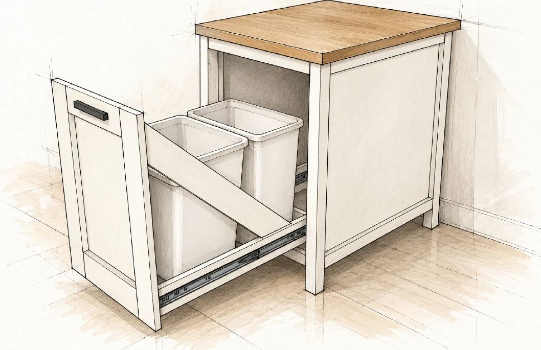
WOODWORKING PLANPullout Bin Kitchen Island
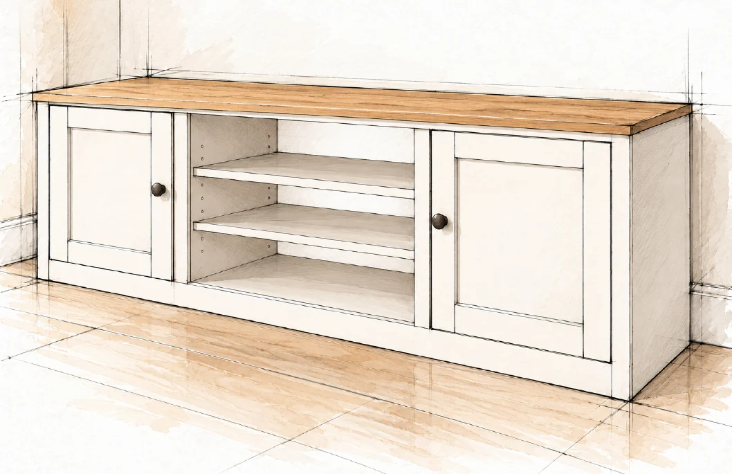
WOODWORKING PLANFarmhouse Media Console
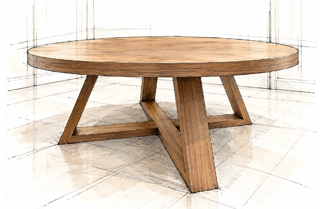
WOODWORKING PLANRound Coffee Table
WOODWORKING PLANGeometric Hairpin Coffee Table
WOODWORKING PLANHollow Panel Waterfall Console
WOODWORKING PLANFarmhouse Console Table
WOODWORKING PLANBarn Door Console
WOODWORKING PLANBeginner Farm Table
WOODWORKING PLANFarmhouse Coffee Table
FREE WOODWORKING PLAN
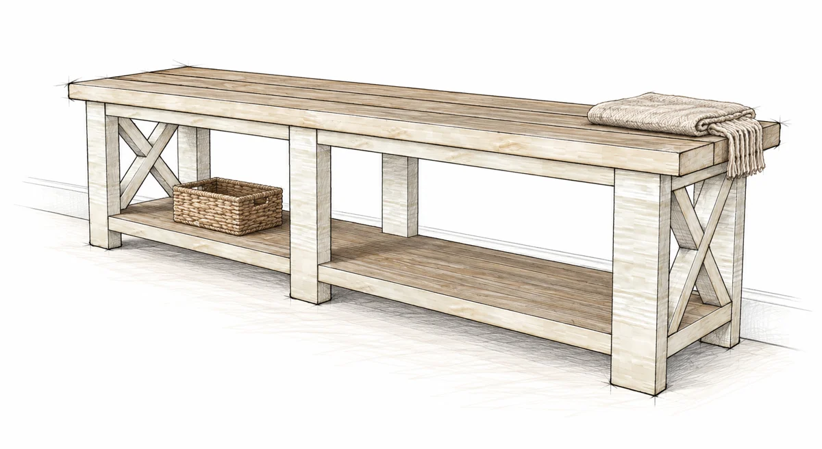
Benches / INTERMEDIATE

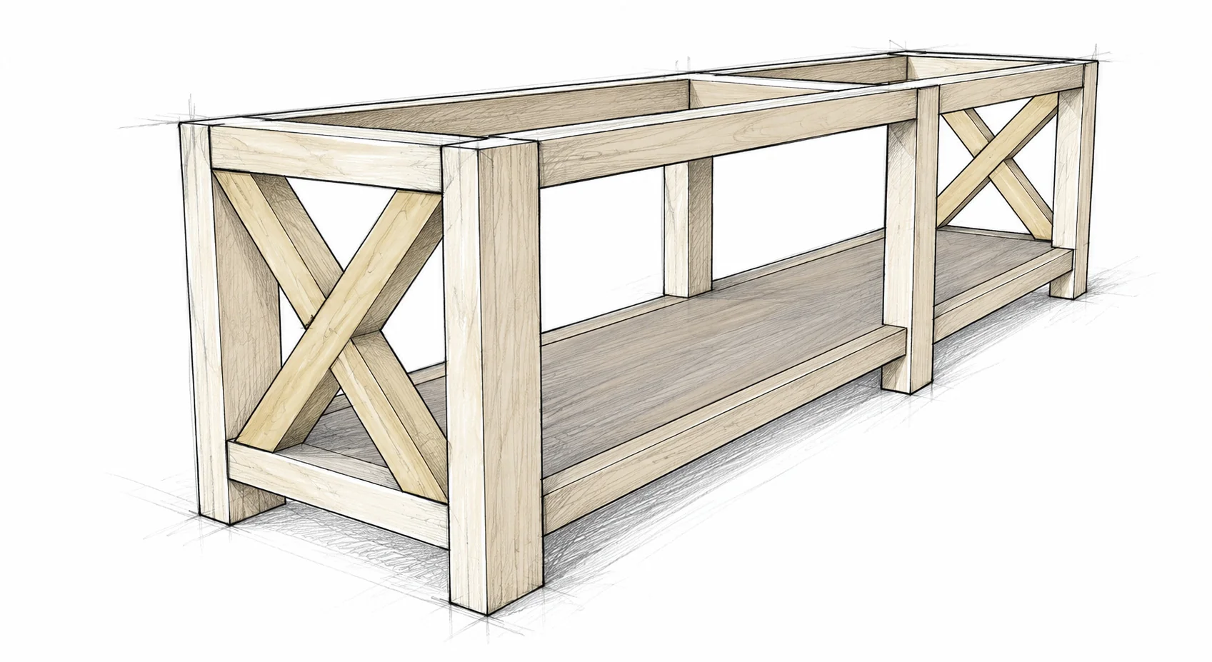
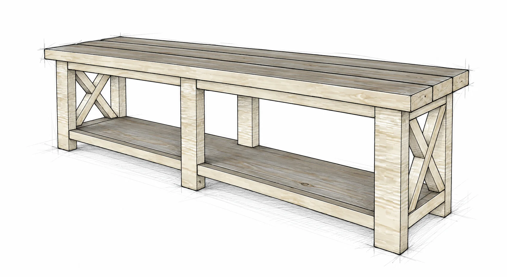
Rustic X Bench

A long bench with a three-board seat, open shelf and X-shaped end details.

FINISHED DIMENSIONS74 1/2 × 16 1/2 × 18 in
SKILL LEVELIntermediate
WHAT IS INCLUDEDMaterials, cut list and illustrated steps
Read the free planMade this plan? Share your build
A GOOD BUILD STARTS WITH A CLEAR PLAN
  • Materials and tools
  • Cutting information and dimensions
  • Illustrated assembly steps
FROM THE FIRST CUT TO THE LAST DETAIL

Take it one step at a time

Everything you need to follow this build is written below. Read the materials, measurements and construction notes before your first cut.

Read the build steps

Yes. The complete plan is available to read on this page.
THE FREE BUILD GUIDE

Rustic X Bench

A long bench with a three-board seat, open shelf and X-shaped end details.

BEFORE THE FIRST CUT

Materials

For the full-length, six-leg version shown here. Choose straight, dry boards without loose knots or splits at joints.

QuantityNominal stockPurchase length
2 boards2×48 ft / 96 in 2438.4 mm
3 boards2×68 ft / 96 in 2438.4 mm
1 board1×126 ft / 72 in 1828.8 mm
4 boards2×28 ft / 96 in 2438.4 mm

Allow for the saw cut

The cut list gives finished part lengths, not rough blanks. Leave room for blade kerf, end trimming and defects when laying out each board. Do not shorten a board before planning all of its cuts.

Keep one 2×2 for the X details

The eight 30 in (762.0 mm) rails fit into three 8 ft boards. Reserve the fourth board for four diagonal blanks, then fit the braces to the completed end openings.

WORKSHOP SETUP

Hardware and tools

Hardware quantities below are practical purchase allowances, not a tested fastening schedule. Keep spare screws for offcut tests.

Buy or prepareUse
100 × 2 1/2 in 63.5 mm pocket screwsFrame and X joints
50 × 1 1/4 in 31.8 mm pocket screws3/4 in (19.1 mm) shelf
25 × 2 in 50.8 mm pocket screwsEdge-joining seat boards
Seat attachment kitType, quantity and layout to confirm before assembly
Glue and finish supplies1 bottle wood glue; abrasives, filler and finish per coverage

Tools

Tape, pencil, square, drill/driver, pocket-hole jig, miter saw, sander, clamps and flat work surface. Add a Forstner bit sized for the figure-eight fasteners, a chisel and suitable pilot bits.

Protection

Eye and hearing protection, suitable dust protection and extraction. Use a drill stop collar and the jig maker’s settings for the actual stock thickness and screw type.

PARTS A TO F

Cut list

Finished lengths. Millimeters are exact inch conversions rounded to 0.1 mm; measure the wood before repeating a cut.

PartQtyStockLength inmmUse
A62×416 1/2419.1Legs
B82×230762.0Long rails
C11×1263 1/21612.9Lower shelf
D52×411 1/4285.8Crosspieces
E32×674 1/21892.3Seat planks
F42×2Fit to openingFit to openingX brace blanks

D is a measured fit

The listed length assumes C is 11 1/4 in (285.8 mm) wide. Make all five D pieces the same length as the shelf width so the two long frames stay parallel.

F becomes six installed pieces

Each end X uses one continuous diagonal and two shorter pieces butted into it. Start with two blanks per end. Trace and fit the ends and the crossing; no fixed brace angle or finished length is specified.

MEASURE THE WOOD YOU HAVE

Nominal and actual sizes

Nominal sizes are shopping labels. The following typical surfaced sizes establish the layout used in this guide.

NominalActual cross-section inActual cross-section mm
1×123/4 × 11 1/419.1 × 285.8
2×21 1/2 × 1 1/238.1 × 38.1
2×41 1/2 × 3 1/238.1 × 88.9
2×61 1/2 × 5 1/238.1 × 139.7

Calculated checks for standard stock

Base: 70 1/2 × 14 1/4 in (1790.7 × 362.0 mm). The three legs across each long face contribute 10 1/2 in (266.7 mm); two 30 in (762.0 mm) bays complete its length.

Shelf height and seat overhang

A level shelf top 3 3/4 in (95.3 mm) above the feet leaves 11 1/4 in (285.8 mm) below the upper rails. Centering the seat gives 2 in (50.8 mm) end overhangs and 1 1/8 in (28.6 mm) front/back overhangs.

Do not scale the sketches

Use written dimensions and measured stock. Loose construction lines explain the assembly, not machining tolerances. If your lumber differs, dry-fit the matching parts and recalculate the checks before fastening.

BEFORE ASSEMBLY

Set up for a safe build

Read all six steps and arrange the labeled parts before drilling. Dry-fit every joint before adding glue.

Cut and drill with support

Clamp the work and support long stock. Keep hands outside the tool maker’s danger zone. Disconnect power before blade changes or adjustments. Let the blade stop before lifting a cutoff or moving a brace.

Set up pocket holes on offcuts

Use 1 1/2 in (38.1 mm) stock settings for the frame, braces and seat; use 3/4 in (19.1 mm) settings for the shelf. These are jig thickness settings, not hole depths. Test screw length and exit position before drilling finished parts.

Keep joints strong

Do not drive screws into split, rotten or loose-knotted wood. Clamp parts square so screws do not pull the joint out of line. Stop if the wood cracks, a screw strips or its point breaks through a visible face.

Plan the finish and location

This guide describes an indoor bench. Follow finish labels for ventilation, drying and oily-rag disposal. Protect nearby surfaces and keep the work area clear when turning the long assembly.

No verified load rating

The design has no tested load capacity stated here. Keep all six feet supported on a level floor. Do not jump, stand on the bench or use it as a ladder. Inspect the completed joints before seating anyone.

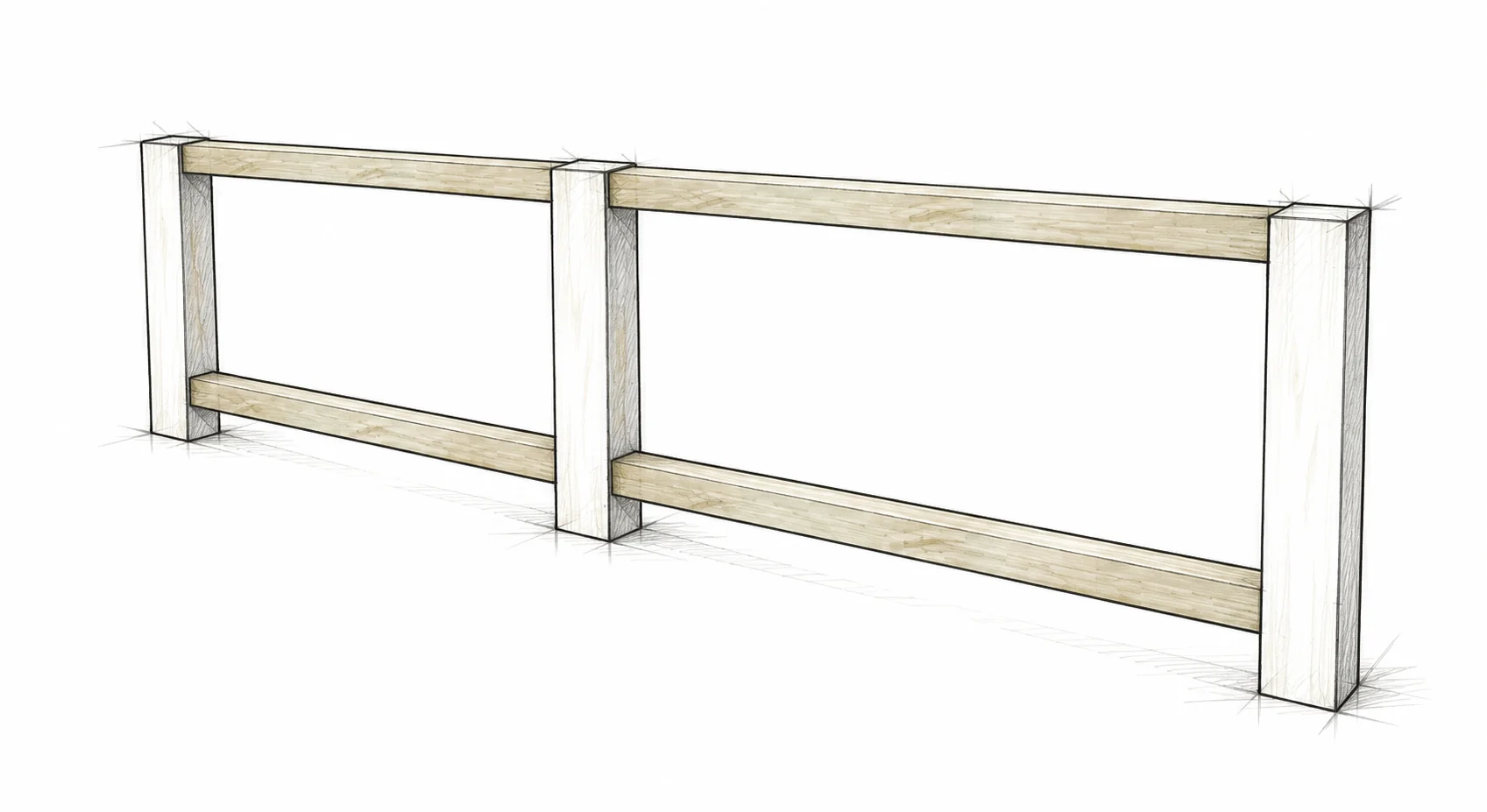
STEP 01 / ASSEMBLY

Build two long frames

A × 6 / B × 8

Build two long frames · Rustic X Bench

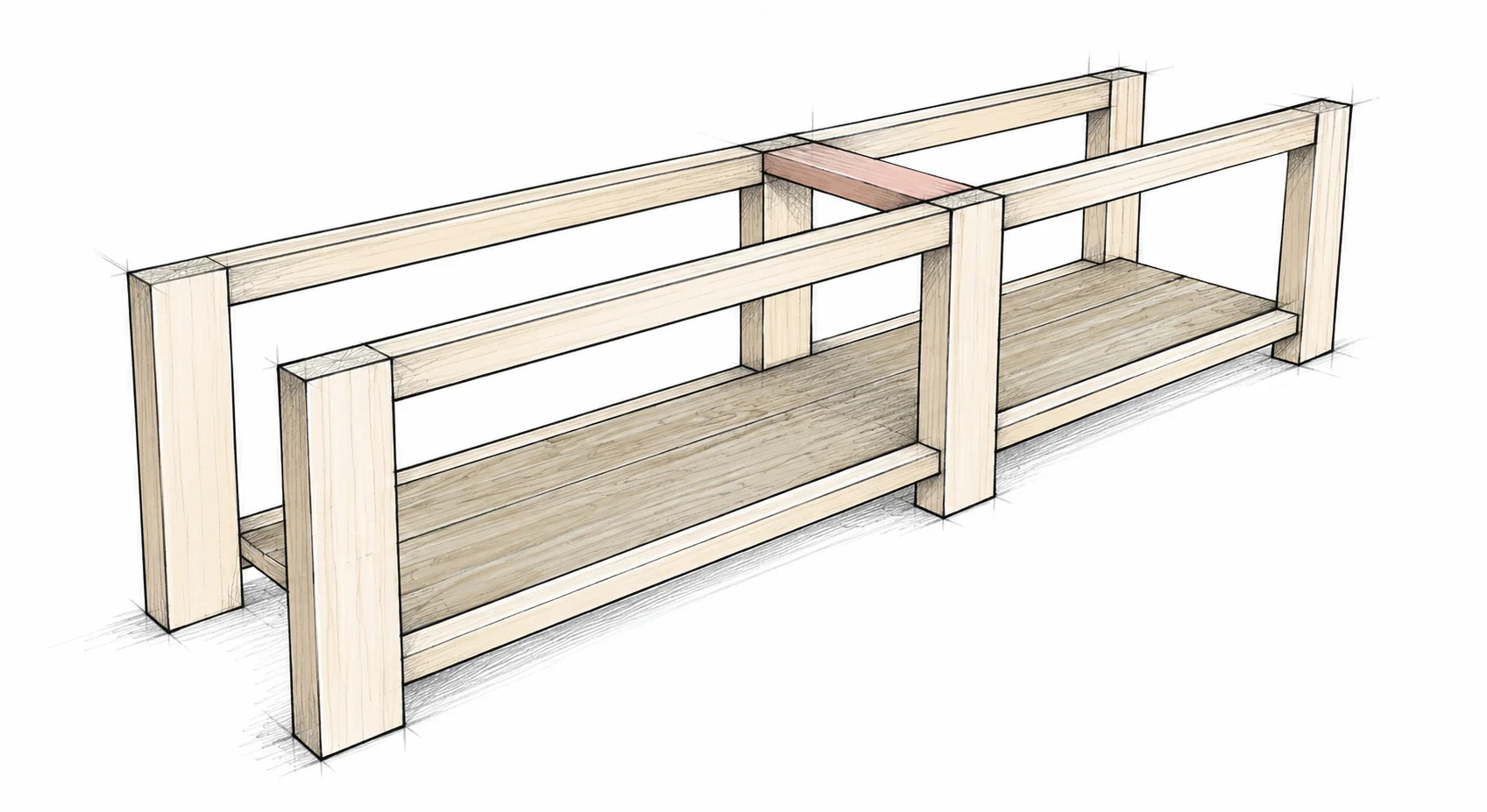
Lay out three legs

Match the lower rails

For each frame, arrange three A legs with their 3 1/2 in (88.9 mm) faces outward. Fit two upper and two lower B rails between them. The two bays are each 30 in (762.0 mm) wide. Keep the upper rails flush with the leg tops.

Set the upper face of every lower rail 3 3/4 in (95.3 mm) above the feet, level with the future shelf top. Drill one pocket hole at each B end. Glue, clamp square and join with 2 1/2 in (63.5 mm) pocket screws. Make two identical frames.

BEFORE YOU CONTINUE

The shelf-height layout is calculated from the 11 1/4 in (285.8 mm) clear opening. Compare both frames before the glue cures.

STEP 02 / ASSEMBLY

Join the frames with the shelf

C × 1 / Two long frames

Join the frames with the shelf · Rustic X Bench

Prepare the shelf holes

Stand and align the frames

Use the jig’s 3/4 in (19.1 mm) setting. Drill pocket holes underneath C along both long edges about every 8 in (203.2 mm), plus two at each end. Keep holes away from defects and stagger them to avoid other fasteners.

Use D pieces as temporary width spacers. Fit C between the long lower rails, with its upper face flush with theirs. Clamp square and attach the long edges with 1 1/4 in (31.8 mm) pocket screws. Leave the end holes for the crosspieces added next.

BEFORE YOU CONTINUE

The shelf ends sit between the end legs. Keep the frames parallel, check both diagonals and support the assembly while fastening.

STEP 03 / ASSEMBLY

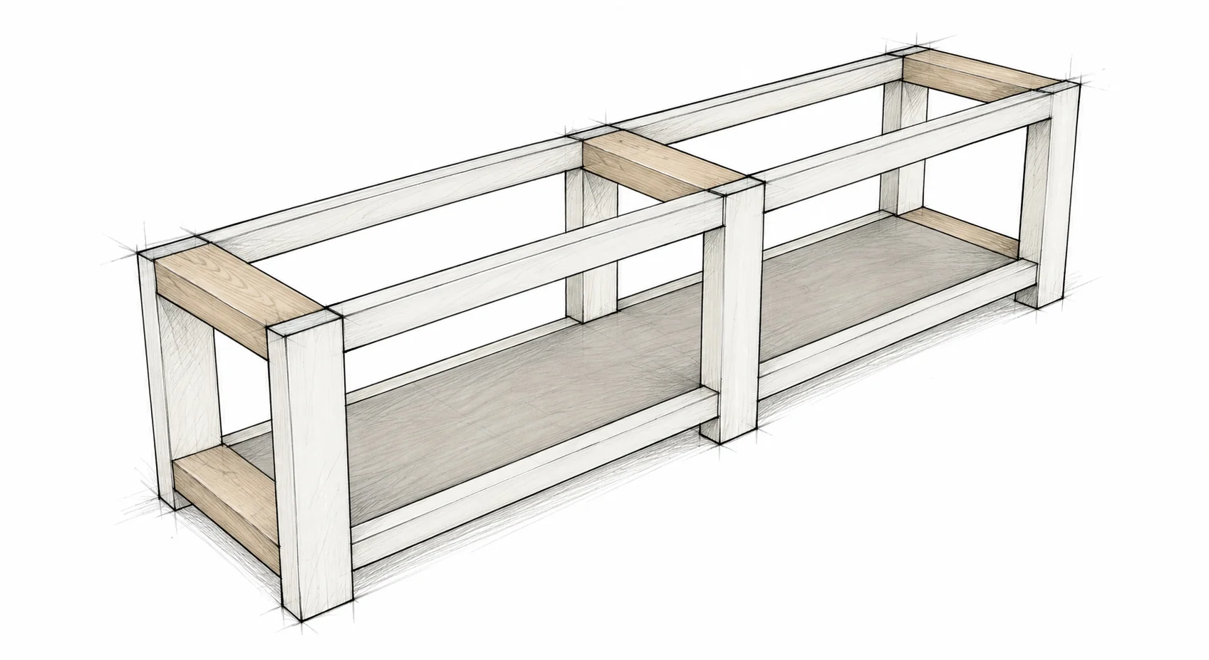
Fit the five crosspieces

D × 5 / Three upper and two lower

Fit the five crosspieces · Rustic X Bench

Place the upper supports

Close the two lower ends

Lay three D pieces flat across the bench: one at each end and one between the center legs. Their broad faces lie horizontal and their upper faces finish flush with the leg tops. Check that each end seats without spreading the frames.

Place the other two D pieces at the lower end openings, with upper faces flush with C. Drill two 1 1/2 in-setting pocket holes per end of every D. Use glue and 2 1/2 in (63.5 mm) pocket screws. Secure the shelf’s end holes into these lower pieces.

BEFORE YOU CONTINUE

Count five D pieces: three above and two below. There is no center lower crosspiece. Keep all six feet on the same plane.

STEP 04 / ASSEMBLY

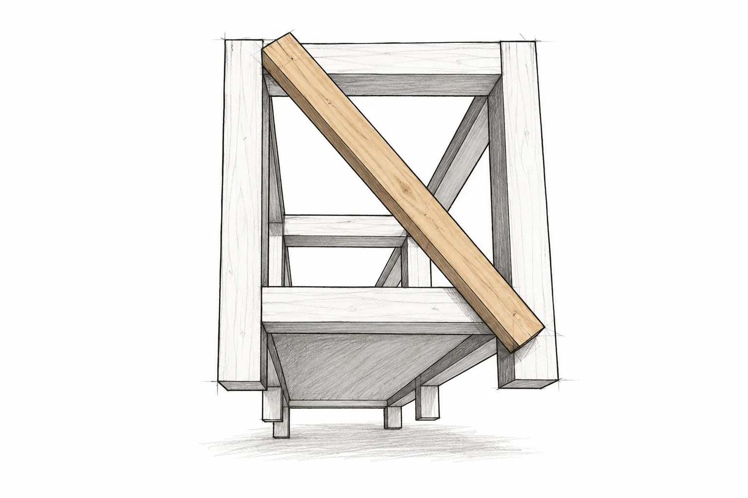
Trace and fit the X pieces

F / Two blanks per short end

Trace and fit the X pieces · Rustic X Bench

Fit one full diagonal

Hold a 2×2 blank across an end opening. Trace where its ends meet the frame. Remove and clamp it safely, cut to the marks, then dry-fit. Do not assume the angle is 45°.

Fit the other direction

Place a second blank across the opening in the opposite direction. Mark its outer ends and the width of the full diagonal where they cross. Cut it into two pieces that butt against the intact diagonal.

Keep each end together

Label the three fitted pieces for that end. Repeat at the opposite end; fit it separately if the opening differs slightly. Do not cut a half-lap.

BEFORE YOU CONTINUE

Each X contains one full diagonal and two short pieces. All three faces must lie in one plane, without forcing the frame out of square.

STEP 05 / ASSEMBLY

Assemble and install both Xs

Two fitted three-piece X assemblies

Assemble and install both Xs · Rustic X Bench

Join each X on the bench

Fix the Xs into the ends

On a flat surface, position the short pieces against the full diagonal. Use the jig’s 1 1/2 in (38.1 mm) setting and one 2 1/2 in (63.5 mm) pocket screw at each center joint. Glue and clamp the faces flush before fastening.

Set one X in each short end opening. Use glue and 2 1/2 in (63.5 mm) screws through the top and bottom supports into the fitted brace ends. Predrill and check each screw path to avoid splits or exposed tips. Recheck the base for rocking.

BEFORE YOU CONTINUE

Keep both long faces open. The Xs belong only at the short ends; neither X replaces a leg or a crosspiece.

STEP 06 / ASSEMBLY

Join and attach the seat

E × 3 / Three continuous top boards

Join and attach the seat · Rustic X Bench

Make the three-board seat

Center the top on the base

Arrange E boards face down with the best faces protected and ends aligned. Edge-join them using 1 1/2 in-setting pocket holes about every 12 in (304.8 mm) and 2 in (50.8 mm) pocket screws. Confirm that screw/jig combination on matching offcuts first.

Confirm a movement-allowing seat attachment; see the option on the next page. With help, place the base upside down on the seat and center it using page 5. Install the chosen hardware as instructed, checking that no screw point reaches the seat surface.

BEFORE YOU CONTINUE

Do not glue the seat to the base or add rigid screws across the grain. Keep the chosen hardware free to accommodate wood movement.

SEAT ATTACHMENT OPTION

Allow for wood movement

Figure-eight tabletop fasteners are one option. No fixed fastening schedule is established here; confirm the hardware for this bench before installation.

1 Confirm the hardware layout

Confirm fastener type, quantity and layout for the chosen hardware and this bench before installation. For figure-eight fasteners, consider bay-facing upper crosspiece edges. Free loops need clear pivot space. Avoid existing screws and pocket holes.

2 Recess the base-side loops

With the base upright, mark and clamp the work. Use the hardware’s specified bit to bore each recess. Seat the base-side loop flush with or just below the support top. Chisel clearance so the projecting loop can pivot.

3 Secure the hardware

Predrill and attach the base-side loops with matching screws. Follow the hardware maker’s recess and pilot-hole instructions. Do not overtighten: each loop must pivot freely without rising above the support.

4 Fasten the seat from below

Lay the seat face down, center the inverted base and mark the remaining holes. Use a depth stop when drilling the seat pilots, then fit matching screws. Check penetration so no point breaks through the seat.

Check before turning upright

Confirm the chosen layout secures the seat and allows movement. The seat should not lift or rattle. This optional fastening detail does not establish a tested seating load.

FINISH AND INSPECT

Ready for everyday use

Let every glued joint and applied coating reach its specified cure before using the bench.

Prepare the wood

Inspect for loose joints, splits and projecting screw tips. Fill visible holes if painting; for stain, test the filler first. Sand with the grain and soften sharp edges. Remove dust thoroughly without soaking the wood.

Apply the chosen finish

For paint, prime if required and apply thin, even coats. For stain, test on an offcut and wipe off excess as directed; protect with a compatible clear coat. Follow the product’s drying, ventilation and safe-disposal instructions.

Check the assembly

Verify all six feet touch a flat floor. Inspect both Xs, the center legs, seat joints, shelf joints and fasteners. Stop using the bench if it rocks, cracks, loosens or visibly bends; repair the problem before further use.

Care for the bench

Wipe spills promptly. Protect the surface from standing water and hot objects. Check joints and the finish periodically, especially after moving the bench or a major seasonal humidity change.

Keep the intended use modest

No tested load limit is supplied. Avoid concentrated loads, jumping and standing on the seat. The lower shelf is for storage, not a step. Keep children from climbing on the bench.

MAKE IT YOURS

Measure your own stock and dry-fit before fastening. If you make this project, I would love to see what you built.

Share your build