WOODWORKING · DIY · A HANDMADE HOME @grainbyjoy
GRAIN by JoyWOODWORKING PLANS · WORKSHOP STORIES · HOME
FIND YOUR NEXT GOOD THING
WOODWORKING PLANPullout Bin Kitchen Island
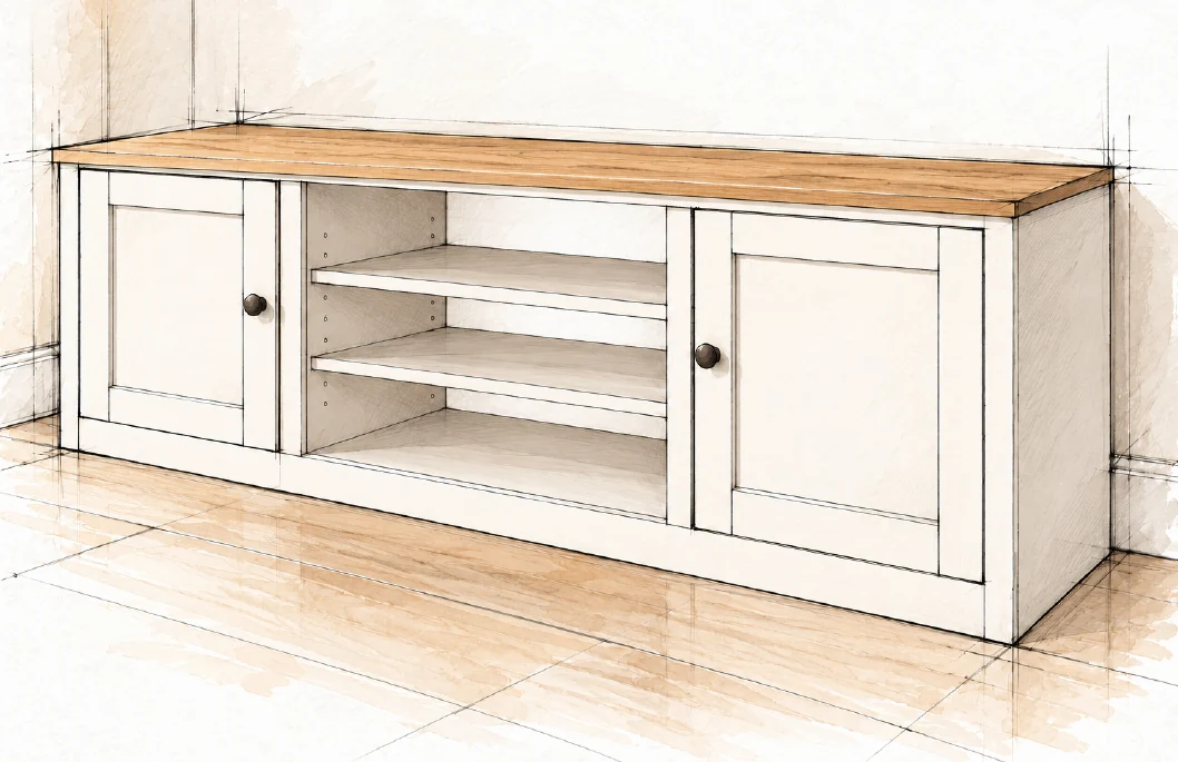
WOODWORKING PLANFarmhouse Media Console
WOODWORKING PLANRound Coffee Table
WOODWORKING PLANGeometric Hairpin Coffee Table
WOODWORKING PLANHollow Panel Waterfall Console
WOODWORKING PLANFarmhouse Console Table
WOODWORKING PLANBarn Door Console
WOODWORKING PLANBeginner Farm Table
WOODWORKING PLANFarmhouse Coffee Table
FREE WOODWORKING PLAN
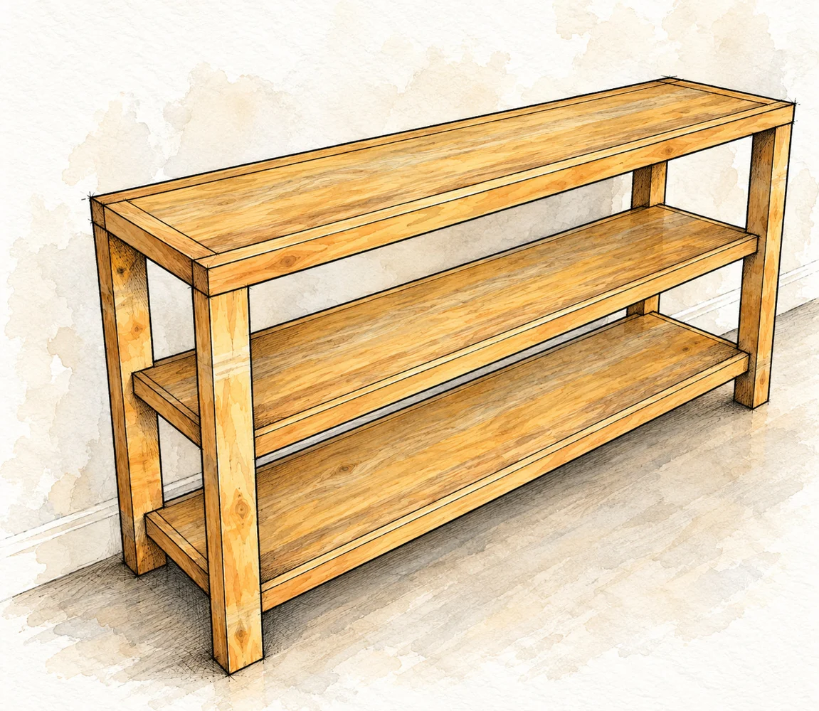
Storage / INTERMEDIATE

Open Shelf Media Console

A narrow media console with a framed top and two open shelves.

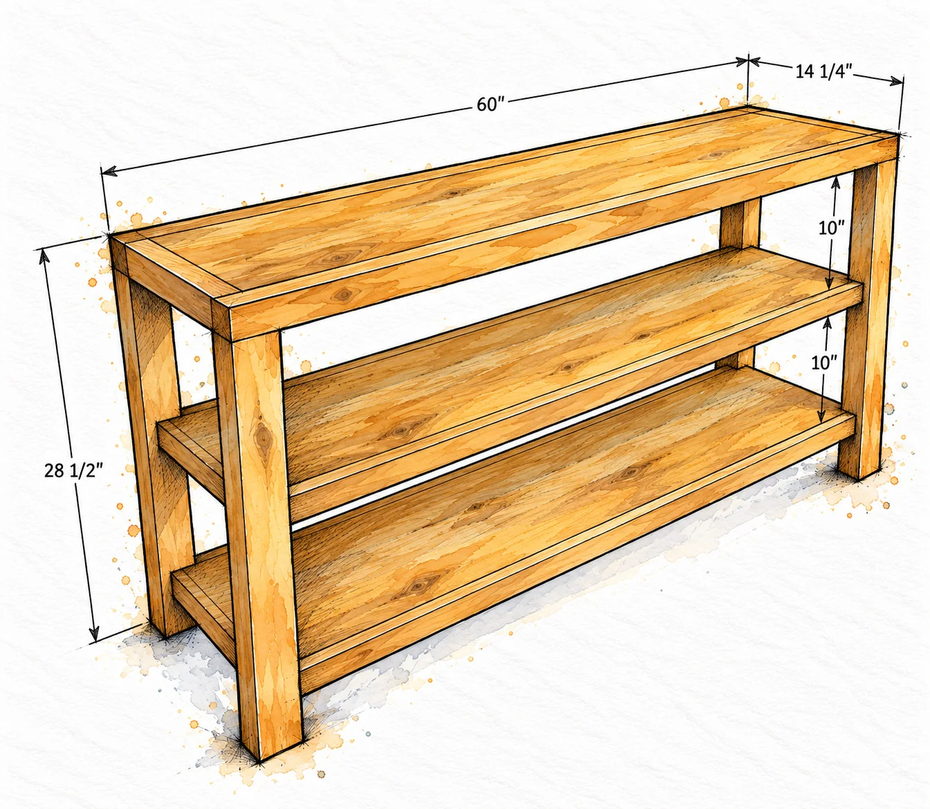
FINISHED DIMENSIONS60 × 14 1/4 × 28 1/2 in
SKILL LEVELIntermediate
WHAT IS INCLUDEDMaterials, cut list and illustrated steps
Read the free planMade this plan? Share your build
A GOOD BUILD STARTS WITH A CLEAR PLAN
  • Materials and tools
  • Cutting information and dimensions
  • Illustrated assembly steps
FROM THE FIRST CUT TO THE LAST DETAIL

Take it one step at a time

Everything you need to follow this build is written below. Read the materials, measurements and construction notes before your first cut.

Read the build steps

Yes. The complete plan is available to read on this page.
THE FREE BUILD GUIDE

Open Shelf Media Console

A narrow media console with a framed top and two open shelves.

PROJECT OVERVIEW

Dimensions and layout

Dimensions and layout · Open Shelf Media Console

Check the footprint

Overall dimensions assume standard surfaced lumber. Both shelf openings have 10 in (254.0 mm) of clear height. The top has a single 11 1/4 in (285.8 mm) wide board inside a fixed 2×2 rim.

The assembly illustrations show the console upside down. The top stays on the bench while the feet point upward. Do not measure from an illustration; use the written dimensions.

BEFORE YOU BUY

Materials

Select straight, dry indoor lumber. Reject splits, badly twisted stock and loose knots at the joints.

Nominal stockBuyRequired yield
2×22 boards × 8 ftTwo 60 in and two 11 1/4 in pieces
1×121 board × 10 ft 1 board × 6 ftThree 57 in boards
2×32 boards × 8 ftFour 27 in legs
1×24 boards × 6 ftFour 55 in and four 11 1/4 in pieces

Fasteners and consumables

1 1/4 in (31.8 mm) and 2 1/2 in (63.5 mm) pocket-hole screws; wood glue; sanding abrasives; optional wood filler; interior paint or stain with a compatible clear finish.

Buy the correct screw type

Use pocket-hole screws matched to your jig and wood species. Screw quantities are not specified. Do not substitute drywall screws. No additional structural hardware is detailed in this build.

PARTS A THROUGH F

Cut list

Cut lengths are finished lengths. All ends are square. Leave allowance for saw kerf and trimming damaged board ends.

PartQtyStockLength inLength mmUse
A22×2601524.0Top front and back
B22×211 1/4285.8Top ends
C31×12571447.8Top and two shelves
D42×327685.8Legs
E41×211 1/4285.8Shelf ends
F41×2551397.0Shelf front and back

Keep the three wide boards separate

Use one C board for the top and one for each shelf. None is made from joined narrow planks. Do not shorten the two shelves to match the 55 in front and back trim.

Mark as you work

Label each part on a hidden face. Mark the best face, the top edge and the waste side of each cut. Check matching parts together before drilling.

MEASURE YOUR OWN BOARDS

Nominal and actual sizes

Nominal labels are purchase names, not measured cross-sections. These are typical dry surfaced sizes.

NominalActual inchesActual millimetres
1×23/4 × 1 1/219.1 × 38.1
1×123/4 × 11 1/419.1 × 285.8
2×21 1/2 × 1 1/238.1 × 38.1
2×31 1/2 × 2 1/238.1 × 63.5

Stock layout with kerf allowance

Each 8 ft 2×2 yields one A and one B. Each 6 ft 1×2 yields one F and one E. Cut two C boards from the 10 ft 1×12 and one from the 6 ft board. Each 8 ft 2×3 yields two legs.

Why two 8 ft wide boards do not work

Two 57 in pieces need 114 in (2895.6 mm) before kerf, so they cannot share an 8 ft board. Three C pieces total 171 in (4343.4 mm); total footage alone does not guarantee a usable layout.

6 ft = 1828.8 mm / 8 ft = 2438.4 mm / 10 ft = 3048.0 mm. Metric values use 25.4 mm per inch, rounded half up to 0.1 mm. Work in one measurement system throughout.

PREPARE THE WORKSHOP

Tools and safe setup

Gather the tools

Tape measure, pencil, square, pocket-hole jig and its stepped bit, drill/driver, compound miter saw and sander. Add clamps, a flat protected workbench and stable support for long boards.

Protect yourself and the work

Wear safety glasses and hearing protection. Use dust extraction and suitable dust protection. Secure loose clothing and hair. Clamp work before cutting or drilling; keep hands outside the tool maker’s danger zone.

Cut and drill safely

Support the board and offcut without trapping the blade. Follow the saw manual for stock wider than its crosscut capacity. Let the blade stop before lifting it. Disconnect power before blade changes or adjustments. Clear chips only with the tool stopped.

Make a practice joint

Match the jig and depth collar to the thickness of the part receiving the pocket hole. Test on matching scraps, check the screw tip cannot emerge and adjust the drill clutch. Clamp faces flush; tighten only until snug, without stripping the pocket.

Illustrations show construction sequence, not exact screw locations or a load test. Muted sage identifies a work area, not a required finish color.

READ BEFORE ASSEMBLY

Solid wood and joint limits

The top is fixed inside a rim

This method fastens one 11 1/4 in (285.8 mm) wide solid board to a four-piece 2×2 rim with pocket screws and glue. It is not a floating panel, and it is not a movement-accommodating breadboard-end design.

Understand the seasonal risk

Solid wood changes width as its moisture content changes. The fixed cross-grain end connections can restrain that movement, creating a risk of checking, splitting or stressed joints. The same concern applies to the fixed solid-board shelves.

Do not treat preparation as a guarantee

Let the lumber acclimate to the intended indoor conditions and avoid large humidity swings. A finish slows moisture exchange but does not stop wood movement. These precautions do not make the fixed connection movement-safe.

Pause if that limitation is unacceptable

Have a qualified furniture maker review a movement-accommodating construction before proceeding. This guide does not invent replacement hardware, a modified joint schedule or an engineered proof of long-term performance.

STEP 01 / ASSEMBLY

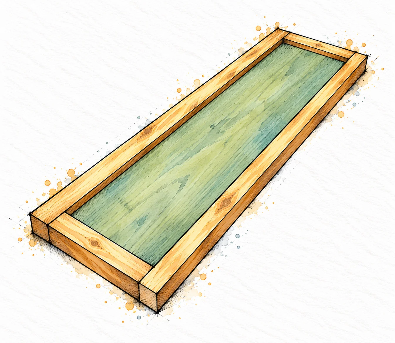
Frame the top

A × 2 / B × 2 / C × 1

Frame the top · Open Shelf Media Console

Drill the concealed face

Set the jig for 3/4 in (19.1 mm) stock and drill around all four edges of C. Set it for 1 1/2 in (38.1 mm) and drill one pocket at each end of both short B pieces.

Join with the top faces flush

On a flat surface, fit B against the ends of C, then fit A along both long sides. Glue and clamp. Use 1 1/4 in screws from C into the rim and 2 1/2 in screws from B into A. Keep the best top faces flush; the underside of C is recessed.

Check Check the four rim corners are square and the single center board has no added seam. Read page 7 before fixing the cross-grain ends.

STEP 02 / ASSEMBLY

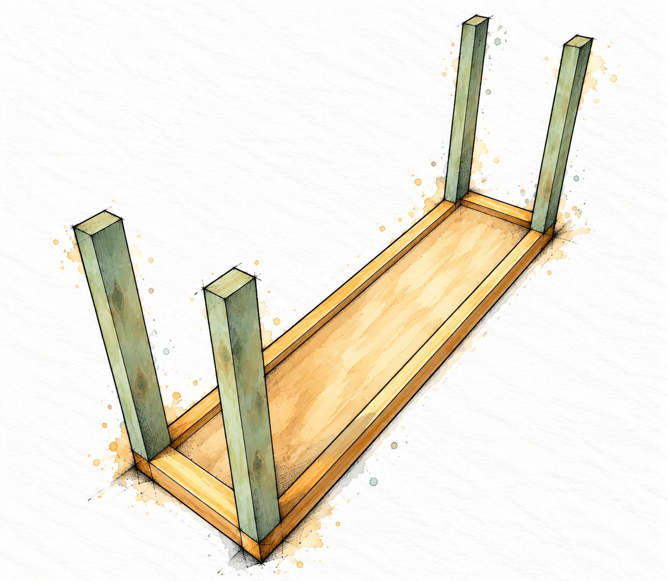
Attach the four legs

D × 4 / Framed top

Attach the four legs · Open Shelf Media Console

Turn the top face down

Protect the finished face on a flat bench. Drill two pockets at one end of each leg with the jig set for 1 1/2 in (38.1 mm) stock.

Set the leg direction carefully

Place each leg under a rim corner. The broad 2 1/2 in (63.5 mm) faces run along the front and back; the 1 1/2 in faces run across the depth. Glue, clamp square and attach to the underside of the rim with 2 1/2 in (63.5 mm) pocket screws.

Check All four 27 in legs point up in the illustration. Do not rotate their cross-sections or screw through the thin center board.

STEP 03 / ASSEMBLY

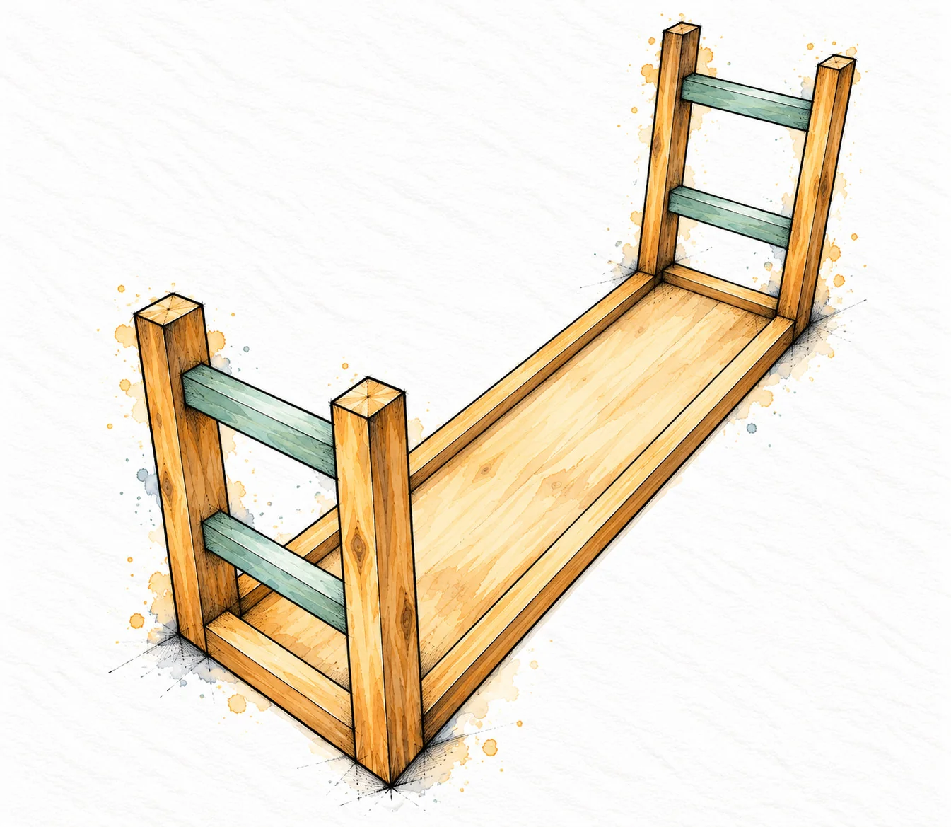
Fit the shelf end trim

E × 4 / Two matching end frames

Fit the shelf end trim · Open Shelf Media Console

Mark from the feet

From each free leg end, mark 4 in (101.6 mm) and 15 1/2 in (393.7 mm). These locate the edge of E nearest the feet: the lower edge when the console stands upright.

Inset and fasten four pieces

Set the outer face of E 3/4 in (19.1 mm) inward from each outer end face of the legs. Use a 1× offcut as a spacer. Drill one 3/4 in pocket at each E end, then glue, clamp and fasten with 1 1/4 in (31.8 mm) pocket screws.

Check Make both ends identical. Keep each 1×2 upright on its 3/4 in edge, with its 1 1/2 in face vertical. Recheck both marks and insets.

STEP 04 / ASSEMBLY

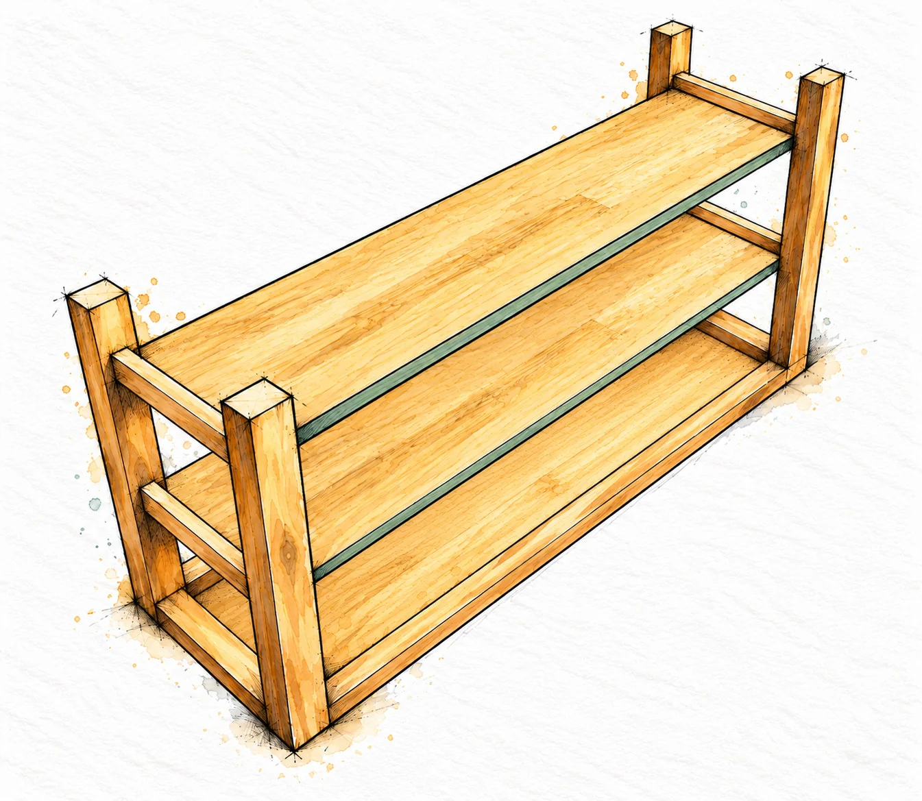
Install the two shelves

C × 2 / One solid board per shelf

Install the two shelves · Open Shelf Media Console

Drill before access gets tight

Set the jig for 3/4 in (19.1 mm) stock. Drill pockets around each shelf, including those aimed into the legs. Along each long edge, space pockets about 8 in (203.2 mm) apart for the trim fitted next.

Seat each shelf in the end trim

Dry-fit the 57 in boards between E pieces. Keep the upper shelf faces flush with the upper edges of E when upright. Glue, clamp and secure to the end trim and legs with 1 1/4 in (31.8 mm) pocket screws. Leave long-edge pockets accessible.

Check Shelf boards remain 57 in long. They are behind the future 55 in front/back trim; no corner notches are needed with the correct leg orientation.

STEP 05 / ASSEMBLY

Add the long shelf trim

F × 4 / Front and back of both shelves

Add the long shelf trim · Open Shelf Media Console

Fit the four 55 in pieces

Set F between the legs, alongside each shelf edge. Keep its 1 1/2 in (38.1 mm) face vertical and its upper edge flush with the shelf surface when upright. Dry-fit before applying glue.

Close the shelf edges

Glue the mating edges and clamp each F flush. Drive 1 1/4 in (31.8 mm) pocket screws through the shelf pockets into F. Check screw paths and remove squeeze-out. With help, turn the console upright after the glue has cured as directed.

Check All four long trims must end against the legs. Check square, level shelves, fully closed joints and four feet on a flat floor before finishing.

ASSEMBLY REFERENCE

The dimensions that must agree

Top and overall height

The 57 in center plus two 1 1/2 in end trims gives 60 in overall length. Across the depth, 11 1/4 + 1 1/2 + 1 1/2 = 14 1/4 in. The 27 in legs plus the 1 1/2 in thick rim give 28 1/2 in overall height.

Why 57 in shelves fit 55 in trim

The 2 1/2 in leg faces reduce the front/back span to 60 - 2 1/2 - 2 1/2 = 55 in. The shelves extend behind those faces. At each short end, the 3/4 in trim and 3/4 in inset leave 57 in for the shelf: 57 + 2(3/4 + 3/4) = 60 in.

Shelf heights from the floor

The lower edges of the shelf trims sit 4 in and 15 1/2 in above the floor. Their 1 1/2 in depth puts the shelf surfaces at 5 1/2 in (139.7 mm) and 17 in (431.8 mm). The two clear openings are 10 in (254.0 mm).

If a part does not fit

Stop and check actual board thickness, leg rotation, trim insets and square. Do not force the shelves, shorten a part at random or move the shelf supports to hide an earlier error.

FINISH THE BUILD

Sand and finish

Prepare every surface

Inspect for split wood, loose screws and sharp edges. Fill visible pockets if desired. Sand with the grain, easing sharp corners without rounding mating joints. Remove dust with a vacuum and a clean cloth suitable for your finish.

Test the complete finish system

Try stain and clear coat, or primer and paint, on an offcut. Filler may take stain differently from the wood. Follow product directions for preparation, application, drying and any light sanding between coats.

Work with ventilation

Use the finish maker’s specified protective equipment and ventilation. Keep products away from ignition sources. Follow the label for storage and disposal of oily rags; never leave them piled together.

Let the coating fully cure

Dry to the touch is not necessarily ready for objects. Wait the stated cure time, then check that the shelves are smooth, screw tips are concealed and the frame does not rock or rack.

BEFORE EVERYDAY USE

Inspect and use safely

Final build check

Verify the rim and shelf joints are closed, legs are square, and all four feet contact the floor. Check for protruding fasteners, split pockets and visible shelf sag. Correct defects before putting the console into service.

No tested load rating

There is no certified capacity or validated TV size for this build. The long shelves are unsupported at the center. Do not assume a safe load from the illustration. Have the completed unit assessed for the equipment you intend to use.

Prevent tip overs

Do not climb, sit or stand on the console. Keep children from pulling or climbing on it. Secure furniture and TVs against tipping using a suitable system selected for the actual wall and furniture; this plan does not specify that hardware or installation.

Care for the wood

Keep the console indoors, away from persistent moisture and strong heat. Wipe spills promptly. Lift with help rather than dragging it. Recheck joints and shelves after moving it and as seasons change; stop use if cracks, looseness or sag develop.

MAKE IT YOURS

Measure your own stock and dry-fit before fastening. If you make this project, I would love to see what you built.

Share your build