Yes. The complete plan is available to read on this page.
THE FREE BUILD GUIDE
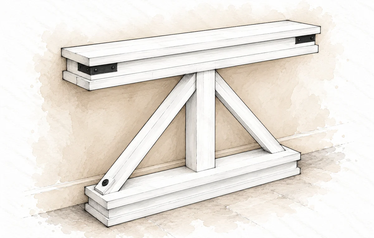
Narrow Truss Console
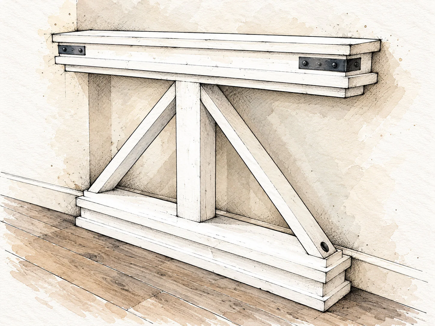
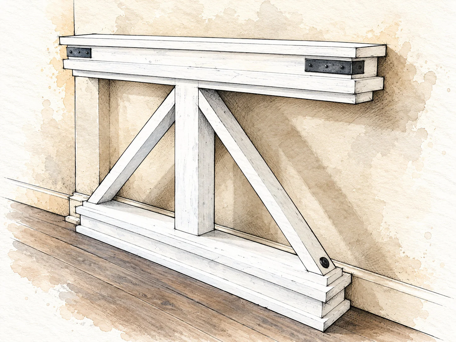
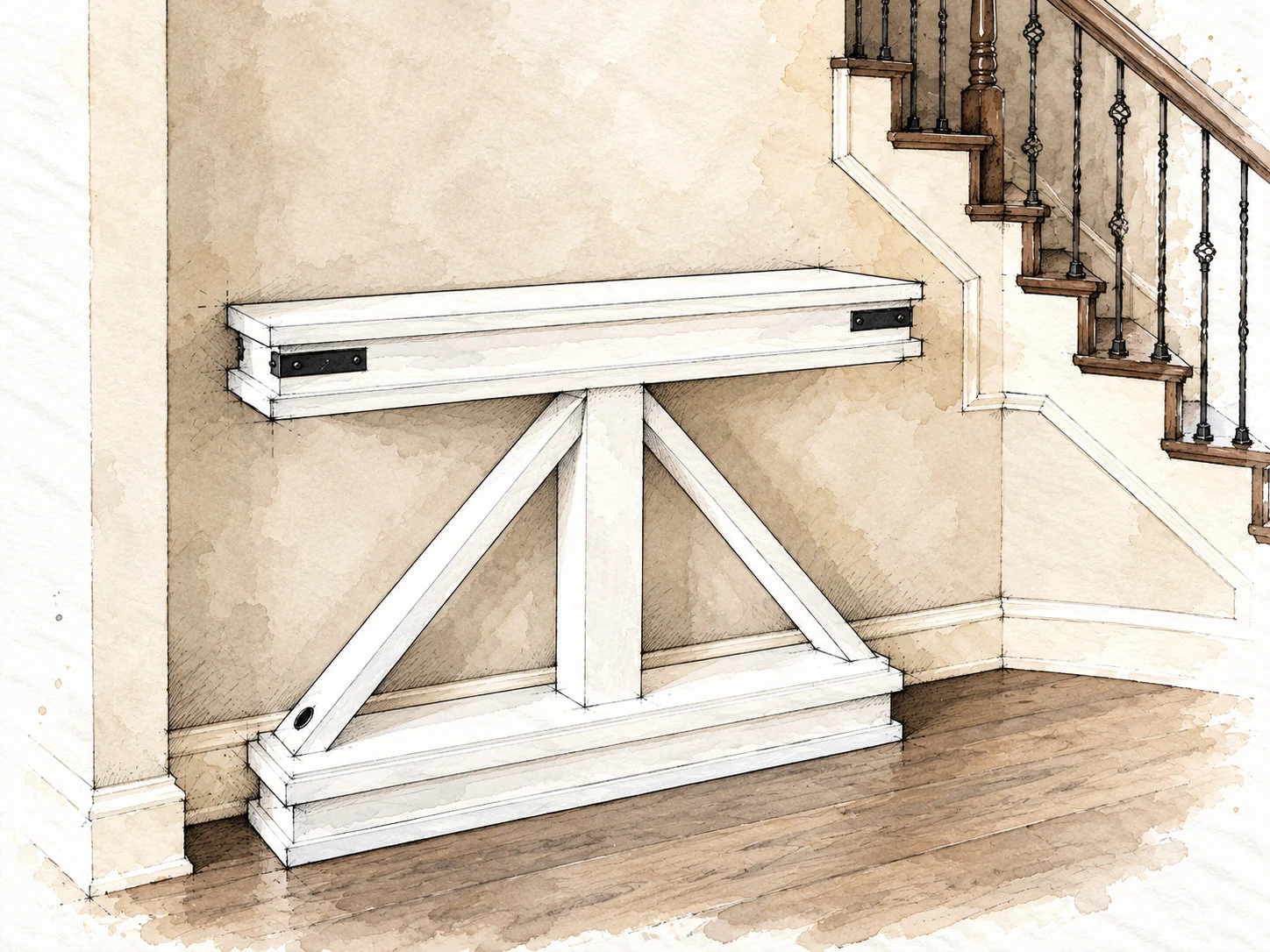
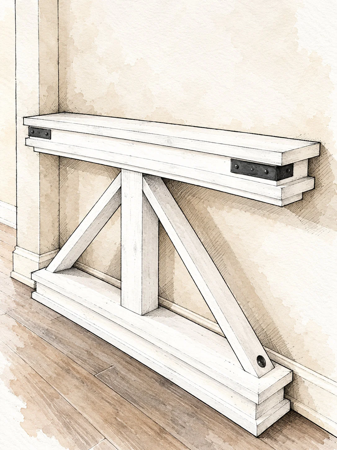
A slim console with layered bases and fitted diagonal trusses.
01 / PROJECT OVERVIEW
Understand the build
What you will make
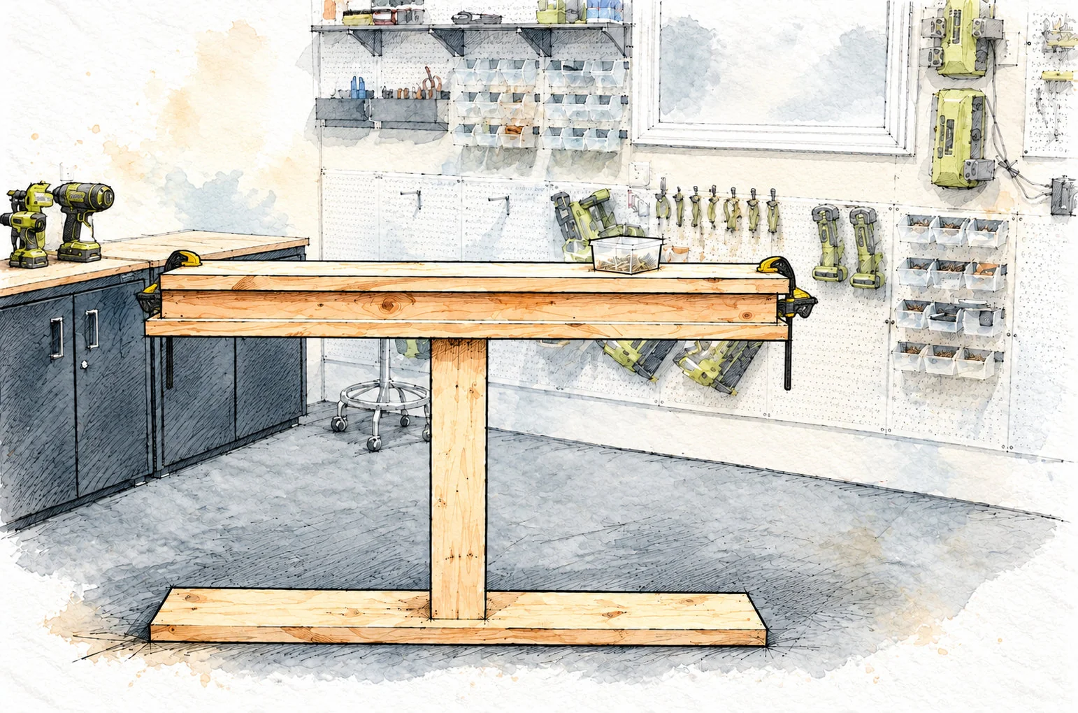
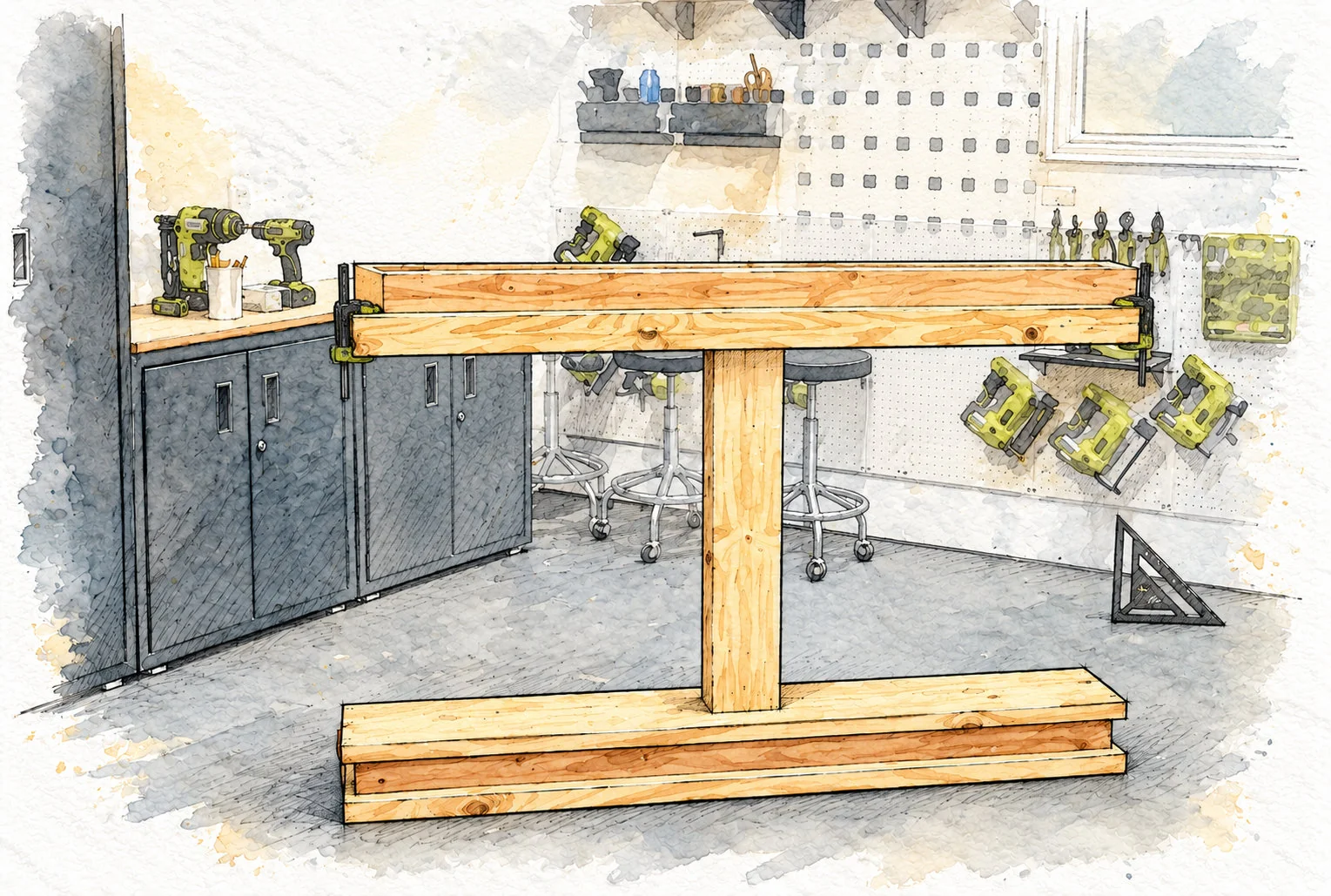
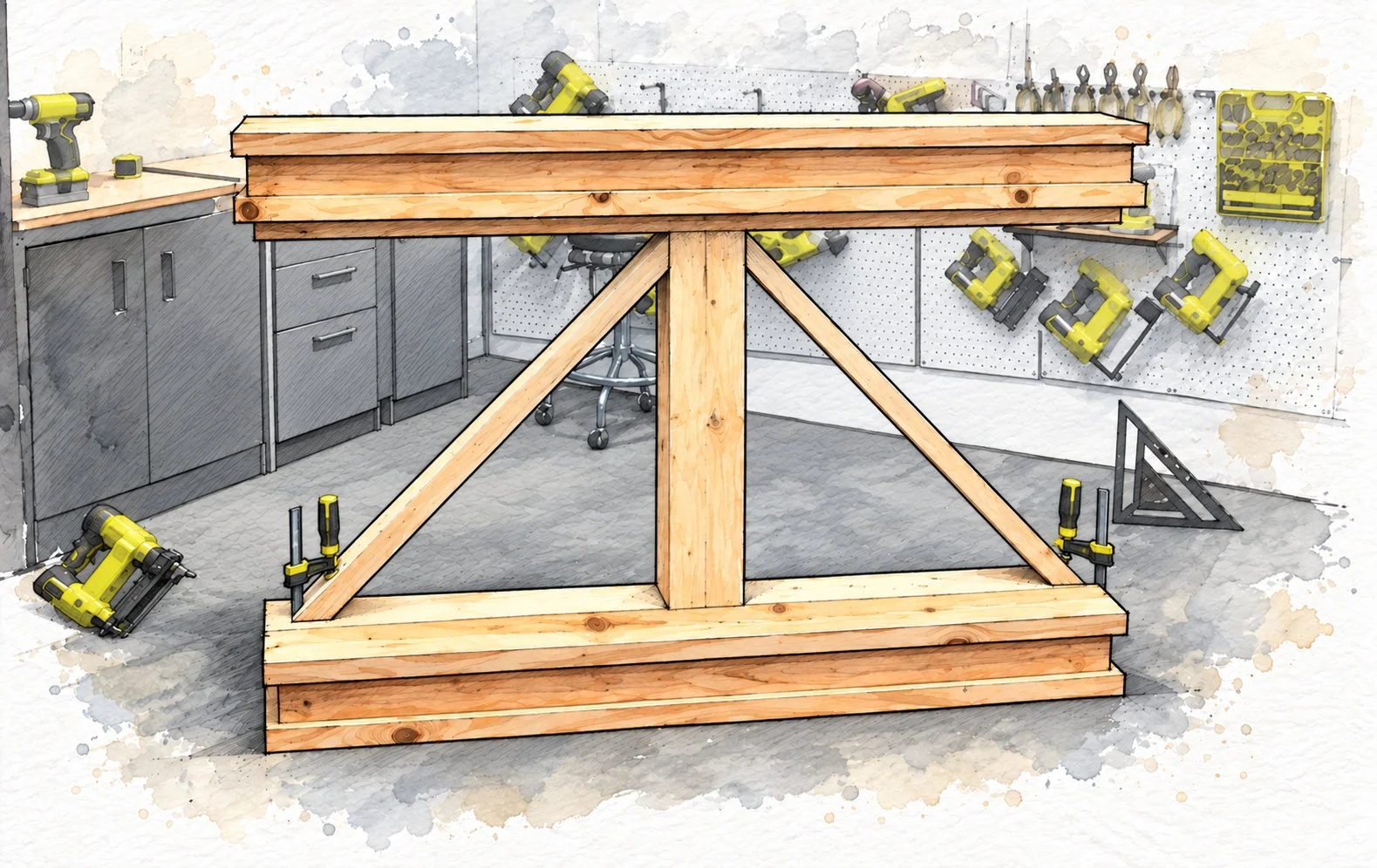
Four wide panels form the top and bottom box assemblies. Each box contains a shallow mitered apron. One laminated center leg connects them. Four horizontal trim pieces and two fitted diagonals complete the truss shape.
Use this guide in order
Prepare materials and cuts on pages 3 to 8. Follow the eleven workshop views on pages 9 to 19; step 4 has two separate views. Finish and secure the console on pages 20 to 24. The cutting map and ten assembly diagrams on pages 25 to 35 provide another view of every stage.
Work from dimensions not illustration scale
Inches are the primary workshop dimensions. Metric values are exact inch conversions rounded to 0.1 mm, not a claim of cutting tolerance. Keep one measuring system throughout a subassembly. The final size check is on page 36.
Plan the installation now
This is tall, very narrow furniture. Choose its wall location and a suitable anti-tip restraint before assembly. Never use the console as a seat, step, climbing frame or television stand. No tested load rating is available.
02 / MATERIALS
Gather the materials
Lumber
• 4 nominal 2×4 boards, 8 ft long • 2 nominal 2×6 boards, 8 ft long • 4 nominal 2×10 boards, 8 ft long Each 8 ft board is 96 in (2438.4 mm) long. Select dry, straight stock without loose knots, splits or serious twist.
Fasteners
• 2 1/2 in (63.5 mm) pocket-hole screws • 3 in (76.2 mm) wood screws • 2 in (50.8 mm) wood screws • 2 1/2 in (63.5 mm) finish nails Fastener counts and screw diameters are not specified. Select suitable wood screws and pocket screws for the wood and jig; do not substitute drywall screws.
Glue and finishing supplies
Wood glue, wood filler, sanding abrasives and a compatible interior paint or stain-and-clear-finish system. Optional corner plates and nail-head accents are decorative only; follow their manufacturer’s fitting directions.
Installation safety item
Provide a furniture anti-tip restraint appropriate to the console and wall construction. Its type, anchors and fasteners depend on the installation; do not infer them from the decorative hardware shown in the illustrations.
03 / WORKSHOP SETUP
Tools and safe working
Cutting and joining tools
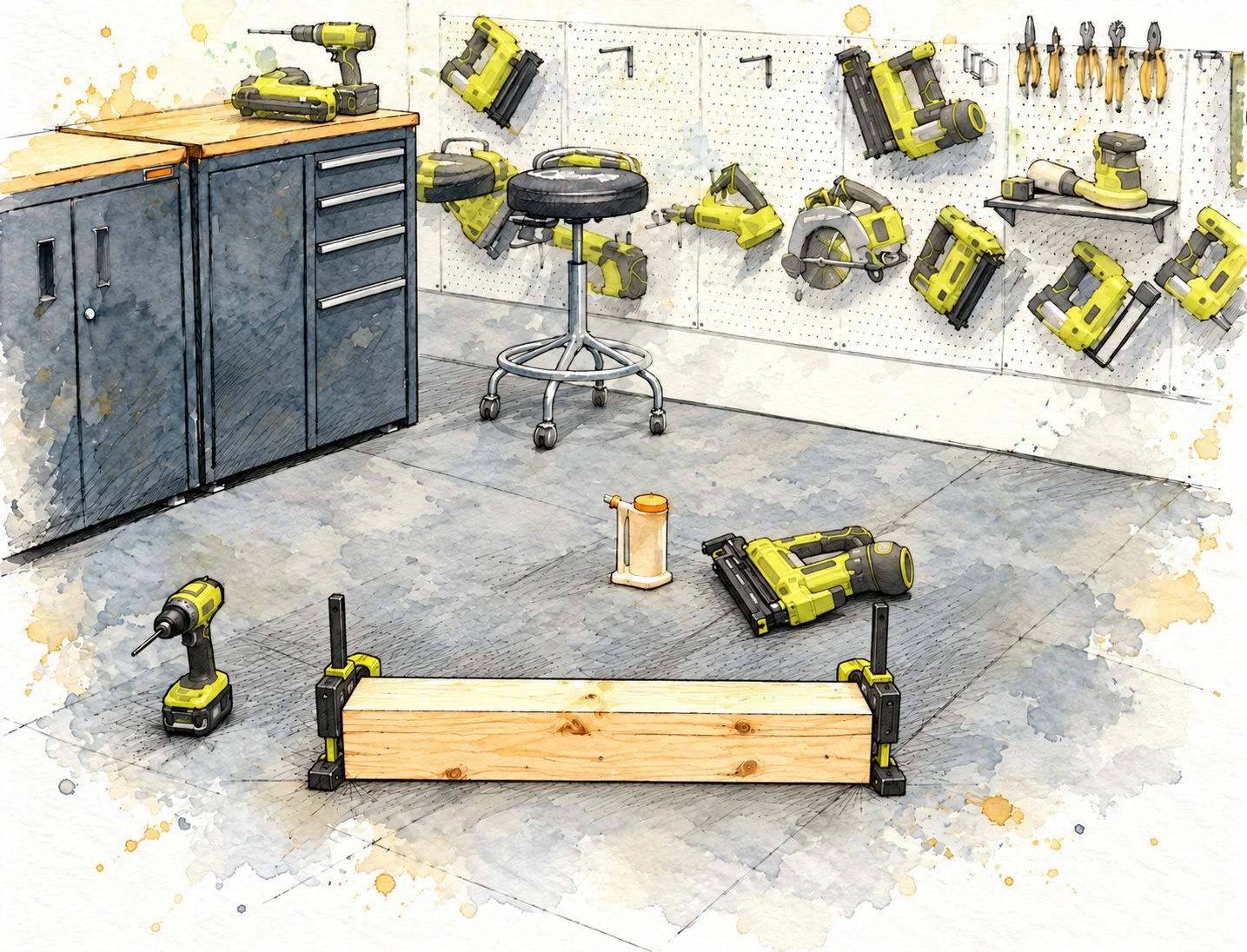
A suitable crosscut or miter saw; table saw for ripping; drill/driver and bits; countersink bit; pocket-hole jig; clamps; tape measure; pencil; square; sander; and a finish nailer rated for 2 1/2 in (63.5 mm) nails. A nailer rated only to 2 in cannot fire the specified nails.
Prepare a stable workspace
Use flat supports and outfeed support for long boards. Wear eye and hearing protection; control dust with extraction and suitable respiratory protection. Tie back hair and remove loose clothing. Keep hands clear of blades, drill exits and nail paths.
Use the tools as designed
Follow each tool’s manual. Use guards, a riving knife and suitable push aids for ripping. Never freehand a table-saw cut. Disconnect power before adjustments or clearing jams. If you cannot secure a short or angled piece safely, have a competent shop make the cut.
Handling the assembly
Use clamps and a helper when turning or steadying the console. Do not stand on a base panel to hold it down. Keep the unfinished assembly supported until all joints have set. Never place a hand behind a nail or screw exit path.
04 / KNOW THE STOCK
Nominal and finished sizes
This guide uses the ripped-width version. Do not substitute un-ripped boards without redesigning the assembly.
Stock Typical actual size in Actual size mm
2×4 1 1/2 × 3 1/2 38.1 × 88.9
2×6 1 1/2 × 5 1/2 38.1 × 139.7
2×10 1 1/2 × 9 1/4 38.1 × 235.0
Rip widths for this build
Aprons: 3 in (76.2 mm). Horizontal trim and diagonal blanks: 4 1/2 in (114.3 mm). Wide panels: 9 in (228.6 mm). Center-leg laminations: 5 in (127.0 mm).
Thickness matters
Keep the 1 1/2 in (38.1 mm) stock thickness. Three leg layers make a 4 1/2 in (114.3 mm) deep post. Each top or bottom box is 6 in (152.4 mm) high: 1 1/2 in panel + 3 in apron + 1 1/2 in panel.
Measure before milling
Actual boards can vary. Check thickness, width and straightness. Remove rounded edges evenly where possible, and verify the final width along the whole board before crosscutting.
05 / PARTS A TO F
Cut list
All parts remain 1 1/2 in (38.1 mm) thick. Widths below are finished ripped widths, not nominal board names.
Part and use Qty Width in Length in Length mm
A Center leg 3 5 30 762.0
B Wide panels 4 9 59 1/2 1511.3
C Long aprons 4 3 57 1/2 1460.5
D End aprons 4 3 7 177.8
E Flat truss trim 4 4 1/2 26 1/4 666.8
F Diagonal blanks 2 4 1/2 36 ref. 914.4 ref.
Apron measurements
C and D have opposed 45° end miters forming rectangular frames. Listed lengths are the outside long-point to long-point dimensions. Cut one frame and verify its fit before duplicating it.
Fitted and profiled parts
E has one square inner end and a 30° outer-end profile, leaving a 3/4 in (19.1 mm) short edge. Match the profile on page 25. F is a 36 in reference blank with 45° ends illustrated; mark and cut its final length to the actual opening in step 10.
06 / CUTTING STRATEGY
Keep the useful offcuts
Four 2×4 boards
Rip to 3 in (76.2 mm). Cut one C from each board. The remainder of one board supplies all four D pieces. Mark every long point and allow for the blade kerf; do not lay consecutive cut marks with no allowance for material removed by the saw.
Two 2×6 boards
Rip to 4 1/2 in (114.3 mm). One board supplies the two F reference blanks. The other supplies three E pieces. Leave diagonal stock long until the frame is built and the actual fit can be marked.
Four 2×10 boards
Rip each panel portion to 9 in (228.6 mm), then cut one B from each board. Save all four long offcuts. Three offcuts supply A, ripped to 5 in (127.0 mm) and cut to 30 in (762.0 mm). The fourth supplies the remaining E, ripped to 4 1/2 in.
Do not cut every angle in advance
Label parts A to F and dry-fit matching pairs. Keep the E end profile and the apron miters distinct. Fit the diagonals only after the boxes and horizontal trim are installed; do not force a nominal blank into a mismatched opening.
07 / BEFORE ASSEMBLY
Orient the parts and joints
Center leg
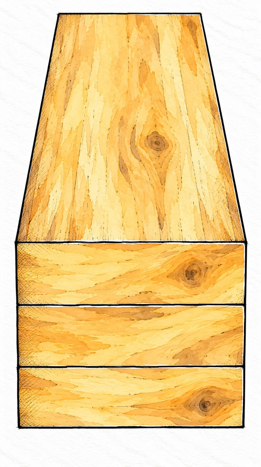
Stack the broad 5 in faces of three A pieces. The finished post is 30 in high, 5 in wide along the console length and 4 1/2 in deep. Keep all three ends flush; uneven ends can tilt the panels.
Apron frames
Each apron stands on its 1 1/2 in edge and is 3 in high. The outside rectangle is 57 1/2 × 7 in (1460.5 × 177.8 mm). A centered frame sits 1 in (25.4 mm) in from every edge of the 59 1/2 × 9 in panel.
Pocket holes and ordinary screws
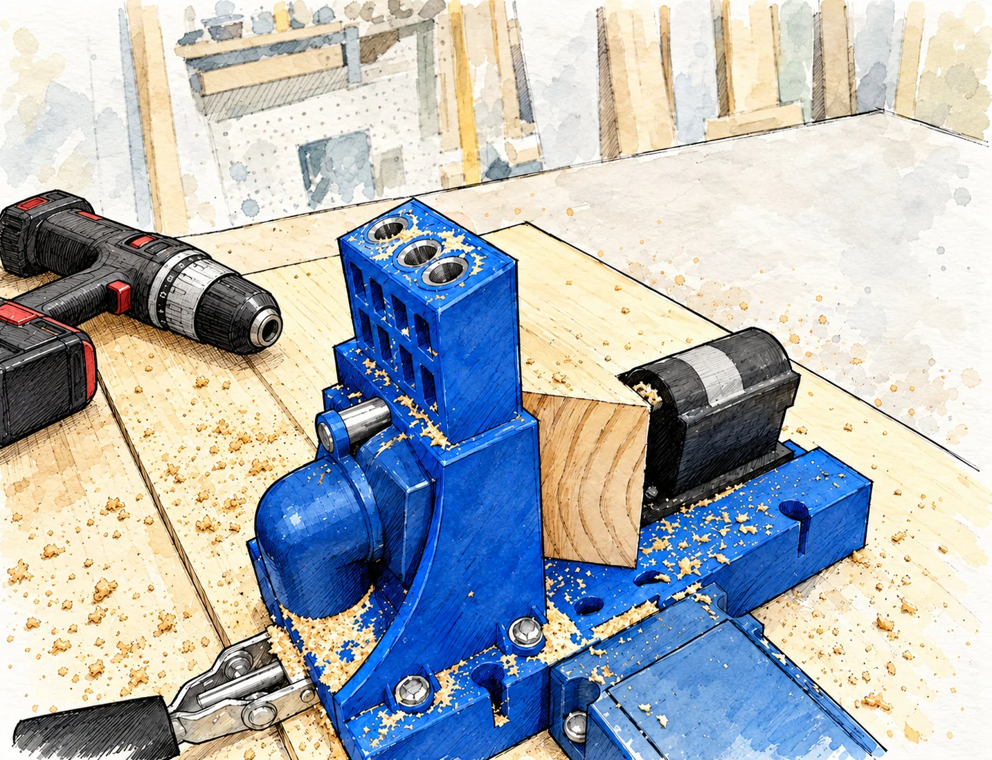
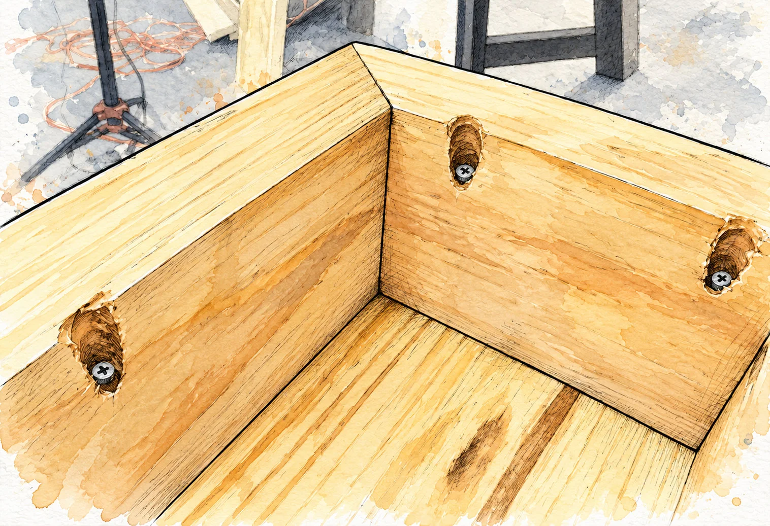
Use the jig setting for 1 1/2 in material, with its matching drill-stop setup and 2 1/2 in pocket screws. Pocket holes go on the inner apron faces and aim toward the panel being attached. Ordinary screws pass through a panel into the receiving wood; predrill and countersink as appropriate.
Glue and test fits
Dry-fit every joint before applying glue. Clamp the faces flush, check squareness and follow the glue label for open, clamp and cure times. Finish nails help hold parts; they do not replace a properly fitted, fully cured glue joint.
STEP 01 / WORKSHOP SEQUENCE
Laminate the center leg
A × 3 / Glue and 2 1/2 in finish nails
Laminate the center leg · Narrow Truss Console
Align the three layers
Lay the three 30 in (762.0 mm) A pieces together with their broad faces touching. Check that the ends and long edges are flush. The combined depth is 4 1/2 in (114.3 mm).
Glue clamp and nail
Spread wood glue over the mating faces and clamp the stack straight. Use 2 1/2 in (63.5 mm) finish nails to secure the layers, keeping nails away from splits and clear of your hands. Remove squeeze-out and let the glue set before handling.
CHECK BEFORE CONTINUING
Check both ends with a square. The three-layer post must not bow, twist or have a stepped end.
STEP 02 / WORKSHOP SEQUENCE
Attach the first wide panel
B × 1 / Glue and 3 in wood screws
Attach the first wide panel · Narrow Truss Console
Mark the center
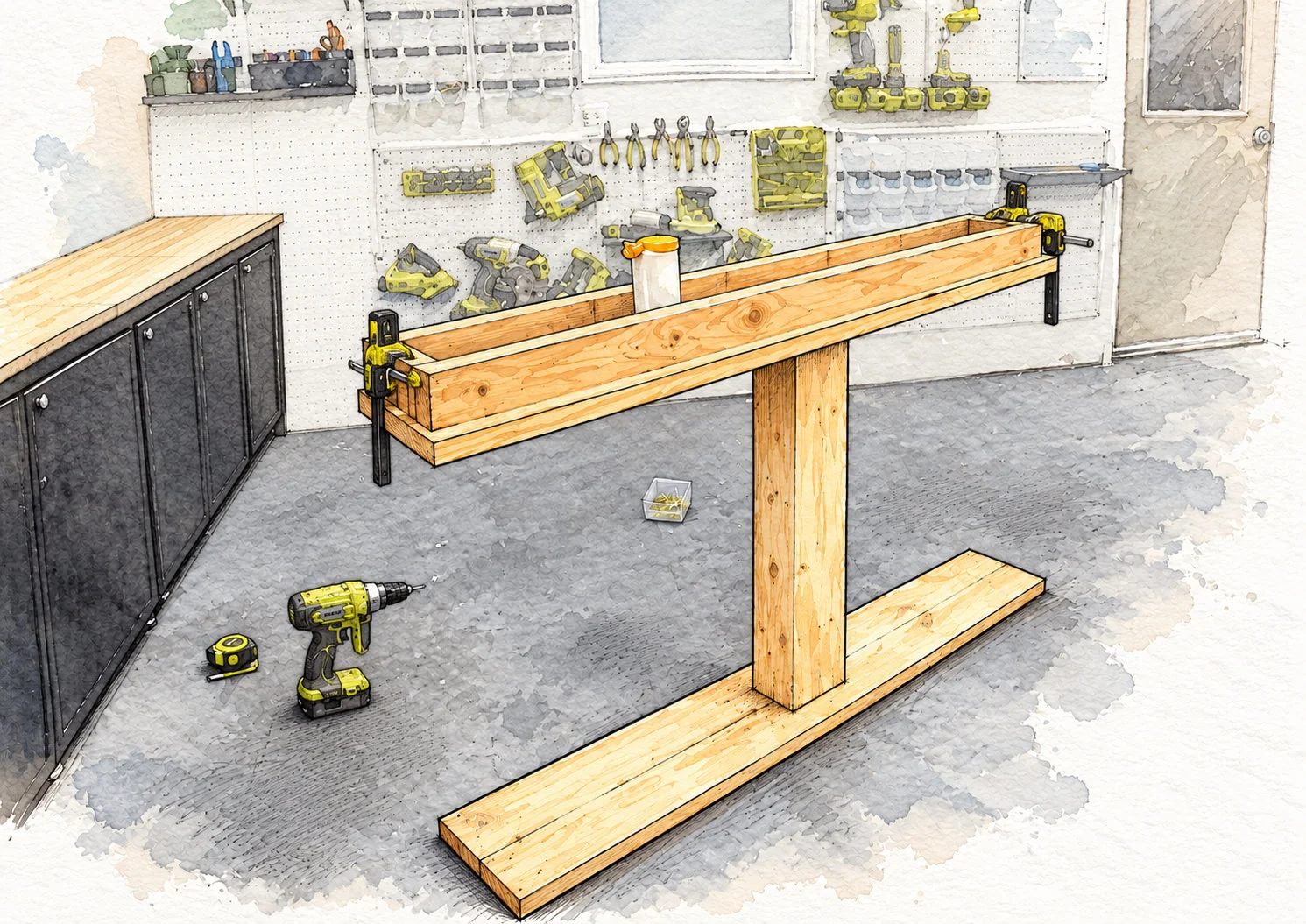
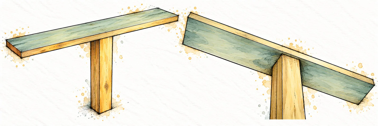
Mark the panel center at 29 3/4 in (755.7 mm) from either end and 4 1/2 in (114.3 mm) from either long edge. Center the end of the laminated post on that point.
Fasten through the panel
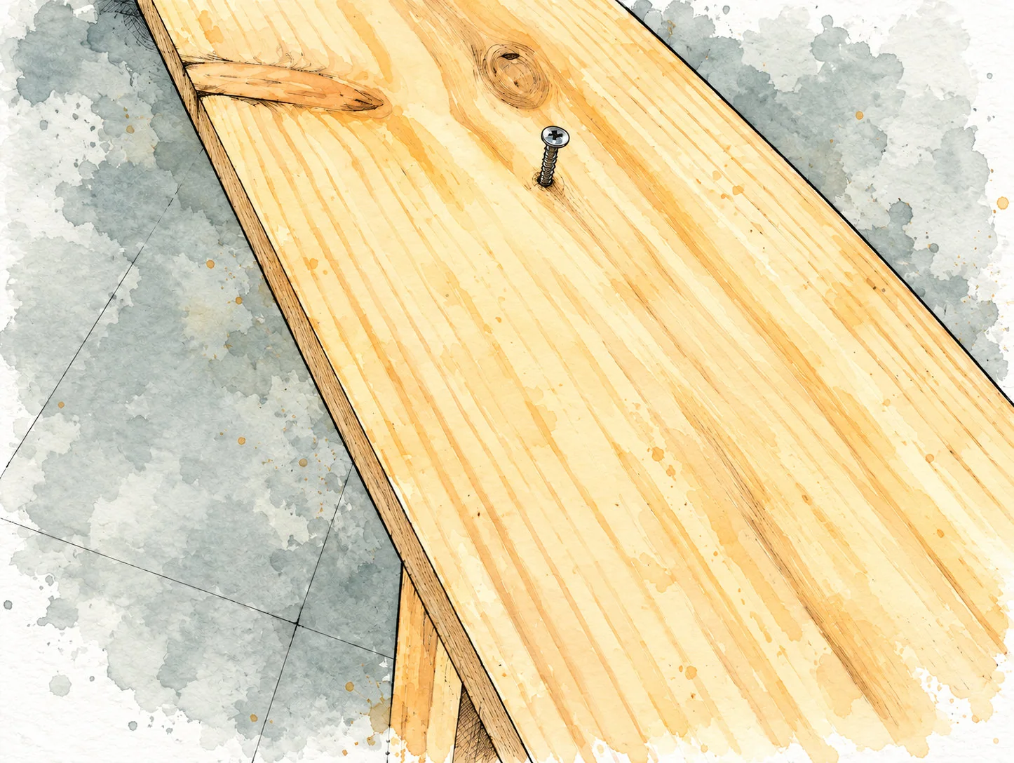
Support the post square to the panel and clamp it. Apply glue, predrill suitable pilot holes and drive 3 in (76.2 mm) wood screws through the outer face of the panel into the leg end. Keep the screw paths within solid wood and away from the edges.
CHECK BEFORE CONTINUING
Check equal overhangs on both sides of the post. Countersink heads without crushing the panel.
STEP 03 / WORKSHOP SEQUENCE
Attach the opposite panel
B × 1 / Glue and 3 in wood screws
Attach the opposite panel · Narrow Truss Console
Turn with support
With a helper, turn the assembly so the other post end is accessible. Support it on a flat surface rather than balancing it on a narrow edge.
Repeat the centered joint
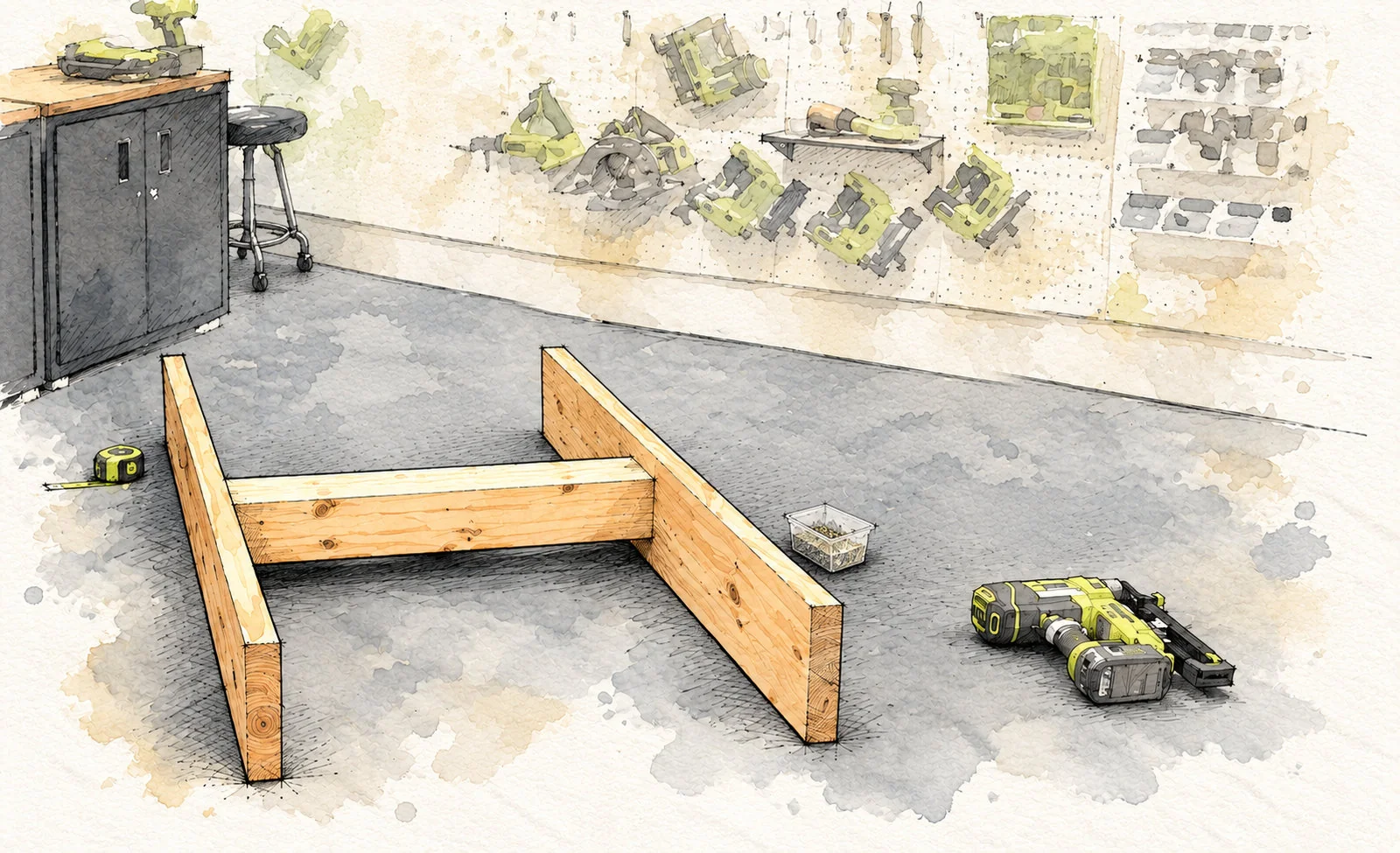
Mark the second panel center as in step 2. Glue and clamp it to the opposite post end. Predrill and drive 3 in (76.2 mm) wood screws through the panel into the post. Align both long panels parallel to one another; do not let one rotate around the center leg.
CHECK BEFORE CONTINUING
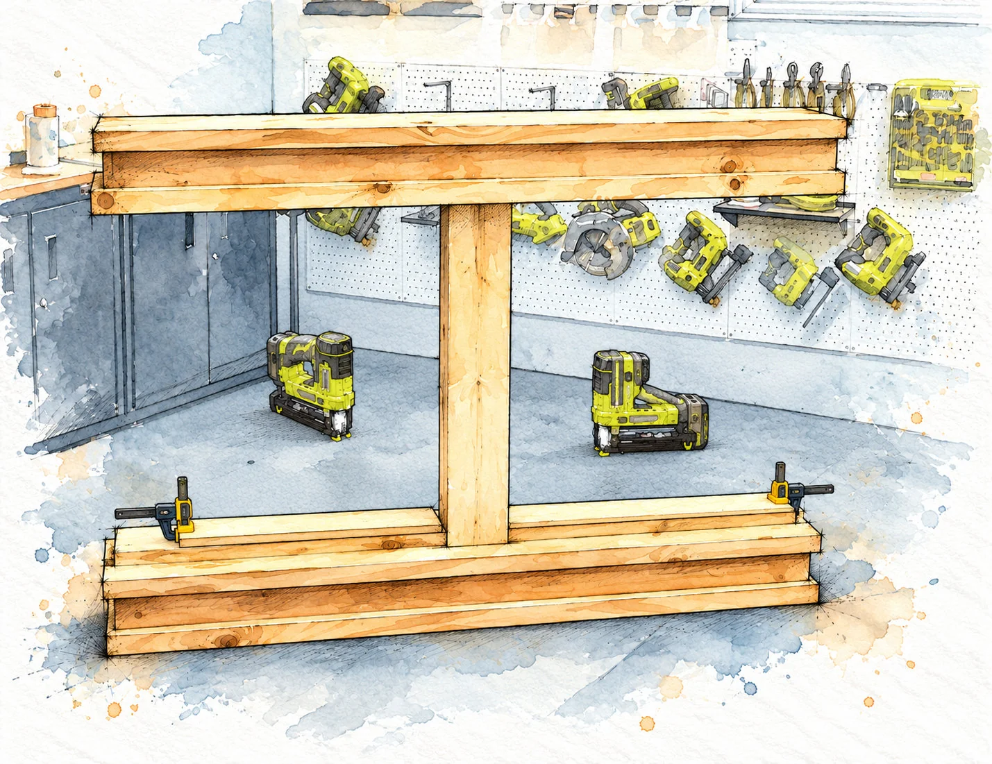
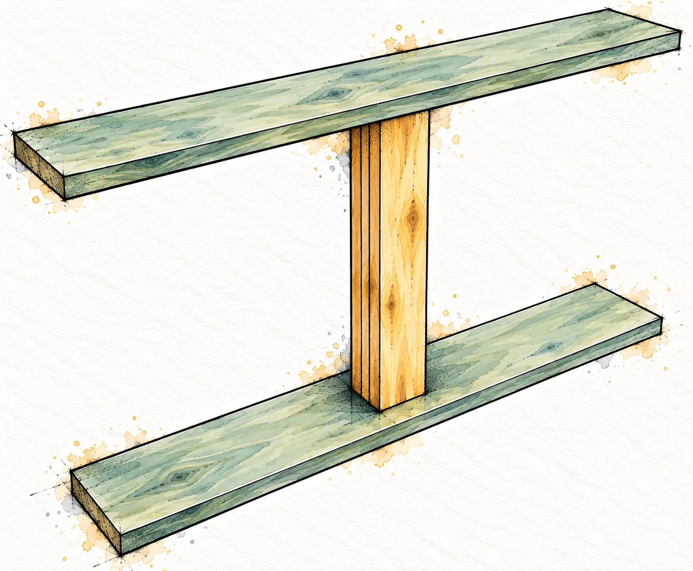
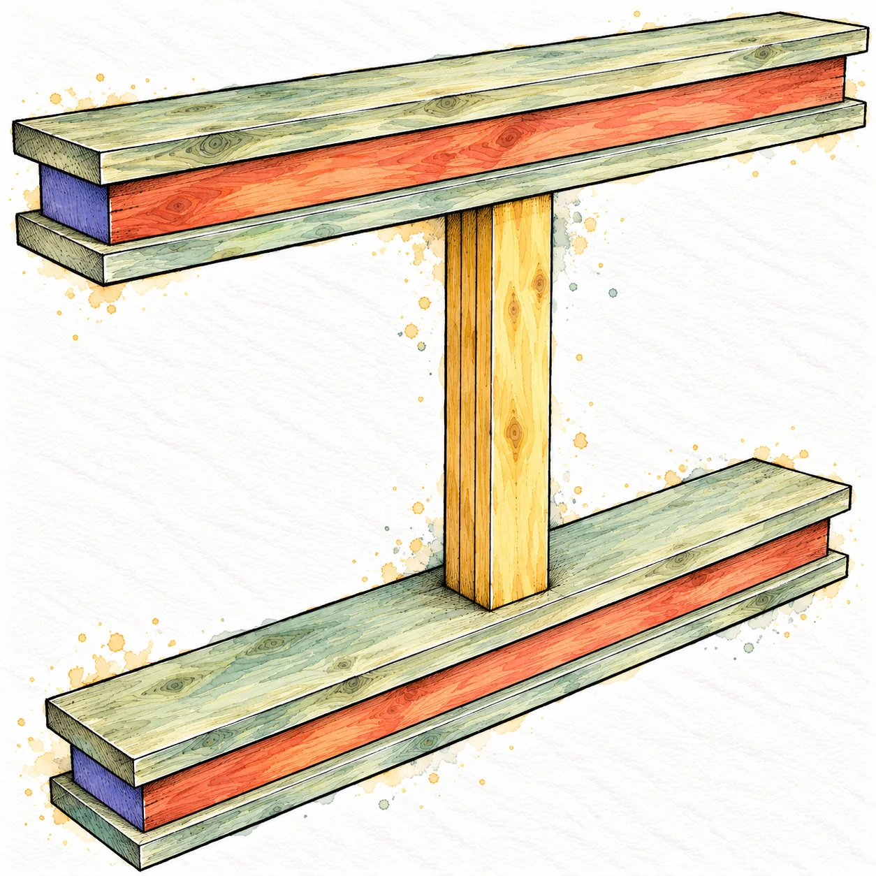
The assembly is an I shape: two single wide panels and one centered post, with no apron or diagonal yet.
STEP 04A / WORKSHOP SEQUENCE
Drill the apron pocket holes
C × 4 / D × 4 / 1 1/2 in jig setting
Drill the apron pocket holes · Narrow Truss Console
Cut the mitered pieces
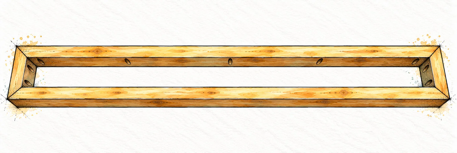
Cut the C and D ends to form two rectangular frames. C is 57 1/2 in (1460.5 mm) long point to long point; D is 7 in (177.8 mm). Dry-fit the first frame before repeating.
Set up the jig
Set the pocket-hole jig and drill stop for 1 1/2 in (38.1 mm) material. Drill along one edge of each apron piece, on the face that will be inside the frame. Aim every pocket toward the same panel-contact edge. Clamp each workpiece firmly while drilling.
CHECK BEFORE CONTINUING
Confirm your jig setup on scrap before drilling the finished parts. Do not put pockets on the visible outer faces.
STEP 04B / WORKSHOP SEQUENCE
Assemble both apron frames
C × 2 and D × 2 for each frame
Assemble both apron frames · Narrow Truss Console
Arrange the four miters
Place two long and two end members on a flat surface. All pocket holes must face inward and toward the same edge. The rectangle stays open in the middle.
Glue and secure the corners
Apply glue at the miter joints, clamp the corners together and compare the two corner-to-corner measurements. Secure the miters with 2 1/2 in (63.5 mm) finish nails. Keep the nail path in the receiving piece and away from your fingers. Make the second frame to match.
CHECK BEFORE CONTINUING
Both frames should lie flat, measure 57 1/2 × 7 in outside and have tight corners without gaps.
STEP 05 / WORKSHOP SEQUENCE
Attach the lower apron
One apron frame / 2 1/2 in pocket screws
Attach the lower apron · Narrow Truss Console
Work with the console upside down
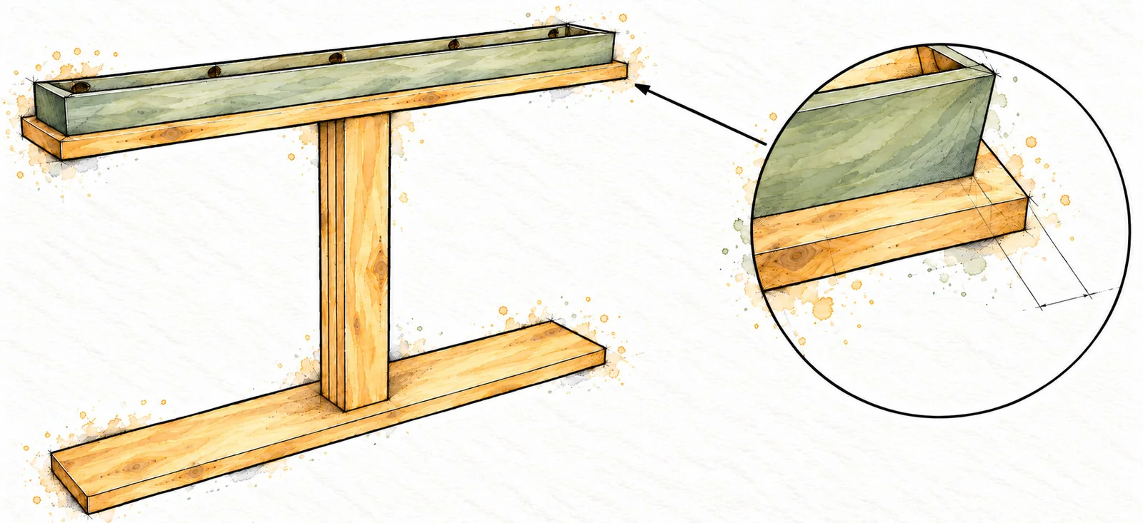
Turn and support the I-shaped assembly so the bottom panel faces upward. Center the first apron on that panel, with a 1 in (25.4 mm) inset from all four panel edges.
Glue clamp and screw
Apply glue where apron edges meet the panel. Clamp the frame in place, recheck the inset, and drive 2 1/2 in (63.5 mm) pocket-hole screws through the apron pockets into the panel. Tighten until the joint closes; do not overdrive or strip the pockets.
CHECK BEFORE CONTINUING
The apron is still open. Every pocket screw points into the wide panel, not out through the visible face.
STEP 06 / WORKSHOP SEQUENCE
Close the lower box
B × 1 / Glue and 2 in wood screws
Close the lower box · Narrow Truss Console
Center the cap
Keep the assembly upside down. Place a third wide panel over the open lower apron. Align it with the panel below so the edges and ends match.
Screw into the apron
Apply glue at the apron’s free edge. Clamp the cap, mark the apron locations, and predrill. Drive 2 in (50.8 mm) wood screws through the cap into the apron, not into the hollow center. Keep heads just below the surface for filling.
CHECK BEFORE CONTINUING
The lower box is panel + apron + panel. It is 6 in (152.4 mm) high, with matching panel overhangs.
STEP 07 / WORKSHOP SEQUENCE
Prepare the upper box
Remaining apron and B panel / Pocket screws
Prepare the upper box · Narrow Truss Console
Build the cap assembly
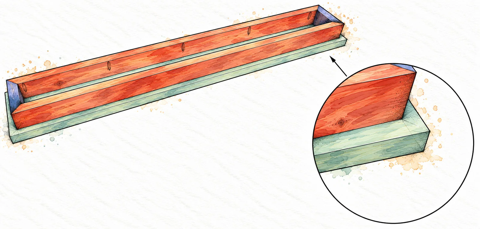
Use the remaining wide panel and second apron as a separate subassembly. Center the apron 1 in (25.4 mm) in from every panel edge. The workshop view shows the open frame and its fastening action.
Keep the interior accessible
Glue and clamp the apron to the panel. Drive 2 1/2 in (63.5 mm) pocket screws from the inner apron faces into the panel. Leave the other side open so it can meet the leg-attached upper panel in step 8.
CHECK BEFORE CONTINUING
Do not seal this apron with another loose board. Its open side fits over the existing upper panel.
STEP 08 / WORKSHOP SEQUENCE
Install the upper box
Upper cap assembly / 2 in wood screws
Install the upper box · Narrow Truss Console
Place the cap assembly
Turn the main console upright with help. Apply glue at the apron’s free edge and place the cap assembly over the upper leg-attached panel. Center it and clamp securely.
Fasten from underneath
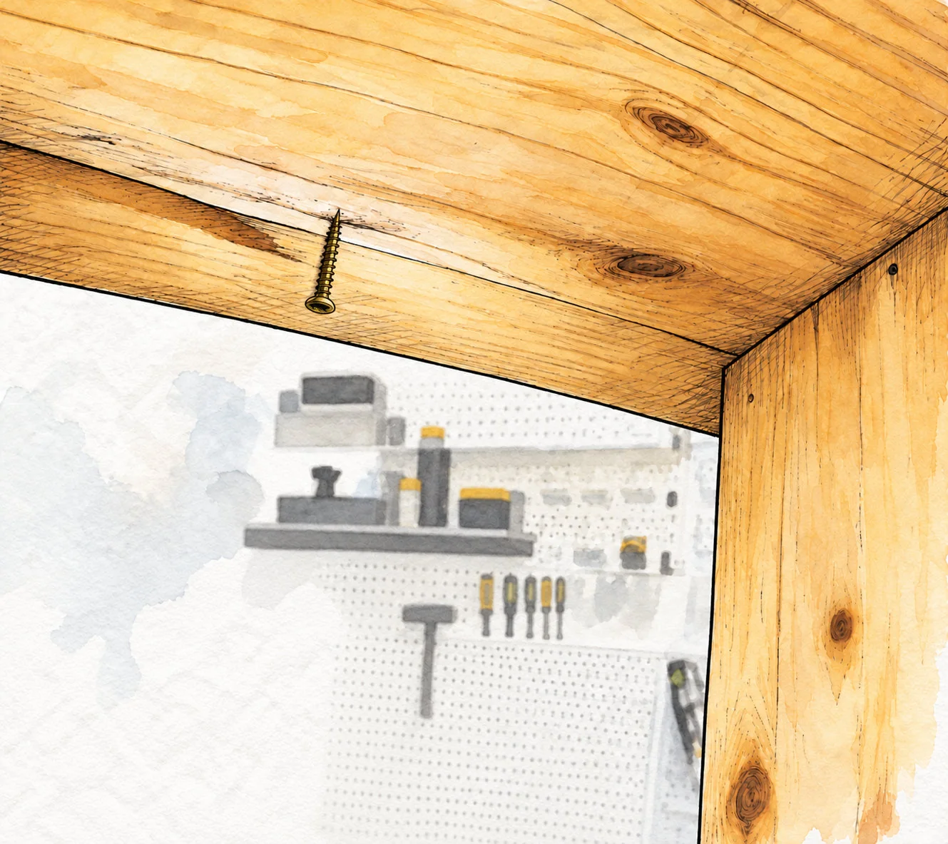
Mark the apron positions on the accessible underside of the upper leg-attached panel. Predrill, then drive 2 in (50.8 mm) wood screws upward through this panel into the apron. Do not try to fasten down through the closed top into an inaccessible hollow space.
CHECK BEFORE CONTINUING
Confirm the screw tips stay inside the apron and do not break through a visible surface. Both boxes should be parallel.
STEP 09 / WORKSHOP SEQUENCE
Attach the horizontal truss trim
E × 4 / Glue and 2 1/2 in finish nails
Attach the horizontal truss trim · Narrow Truss Console
Fit the four flat strips
Prepare the 26 1/4 in (666.8 mm) E pieces with square inner ends and the outer end profile shown on page 25. Place one strip on each side of the post at both the top and bottom bases.
Keep the trim flush
The strips lie flat, broad faces horizontal. Butt their square ends to the post and align their front and back edges flush with the 4 1/2 in (114.3 mm) post depth. Glue, clamp and nail with 2 1/2 in (63.5 mm) finish nails into the wide panels.
CHECK BEFORE CONTINUING
There are four separate strips. None passes through the center post, and the diagonals are not installed yet.
STEP 10 / WORKSHOP SEQUENCE
Fit the two diagonal trusses
F × 2 / Fit cut before glue or nails
Fit the two diagonal trusses · Narrow Truss Console
Mark from the actual opening
Use the 36 in (914.4 mm) dimension as a reference blank, not a guaranteed final length. Hold each blank in its intended position and mark the end cuts from the assembled opening. The illustrated ends are 45°; check the real contact faces before cutting.
Fit without forcing
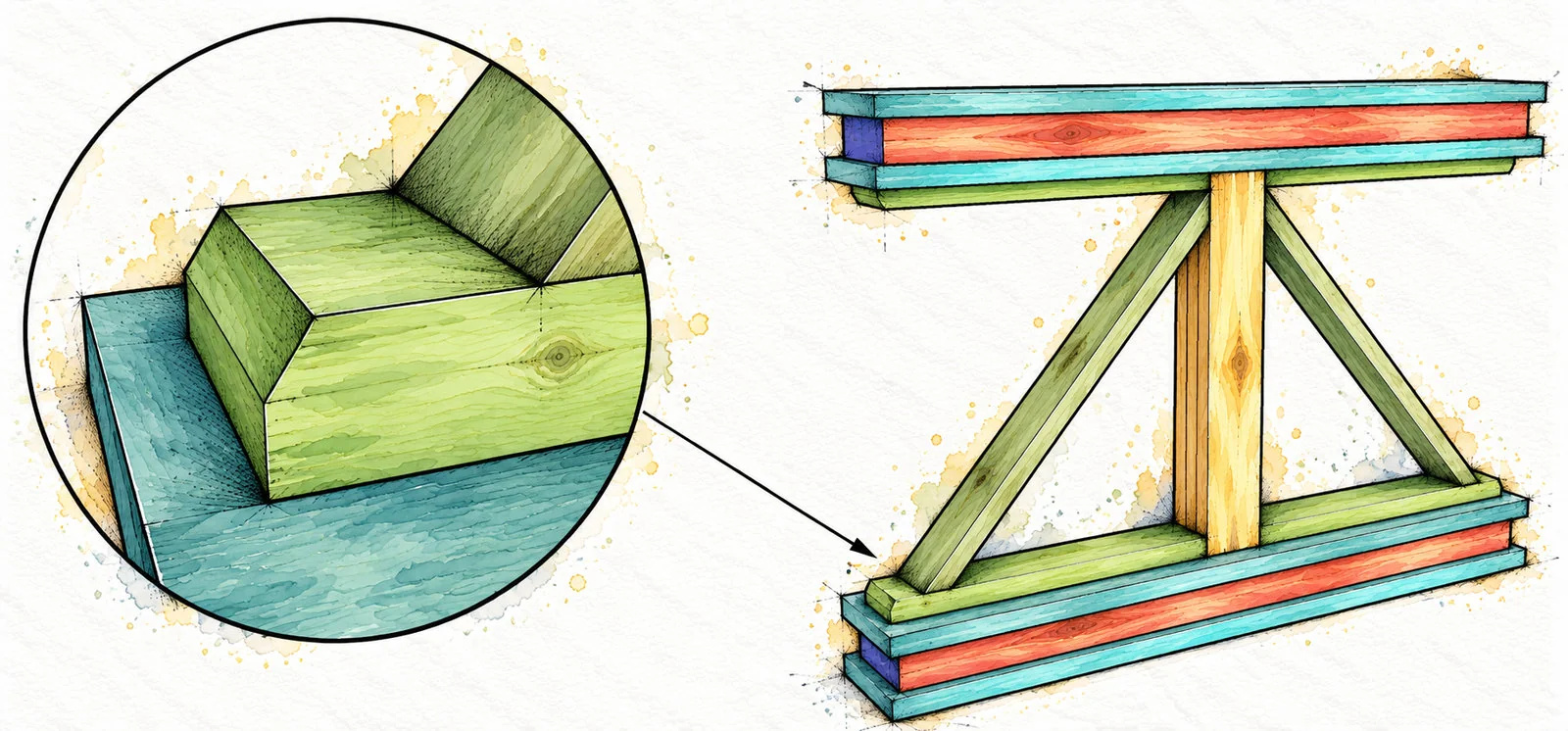
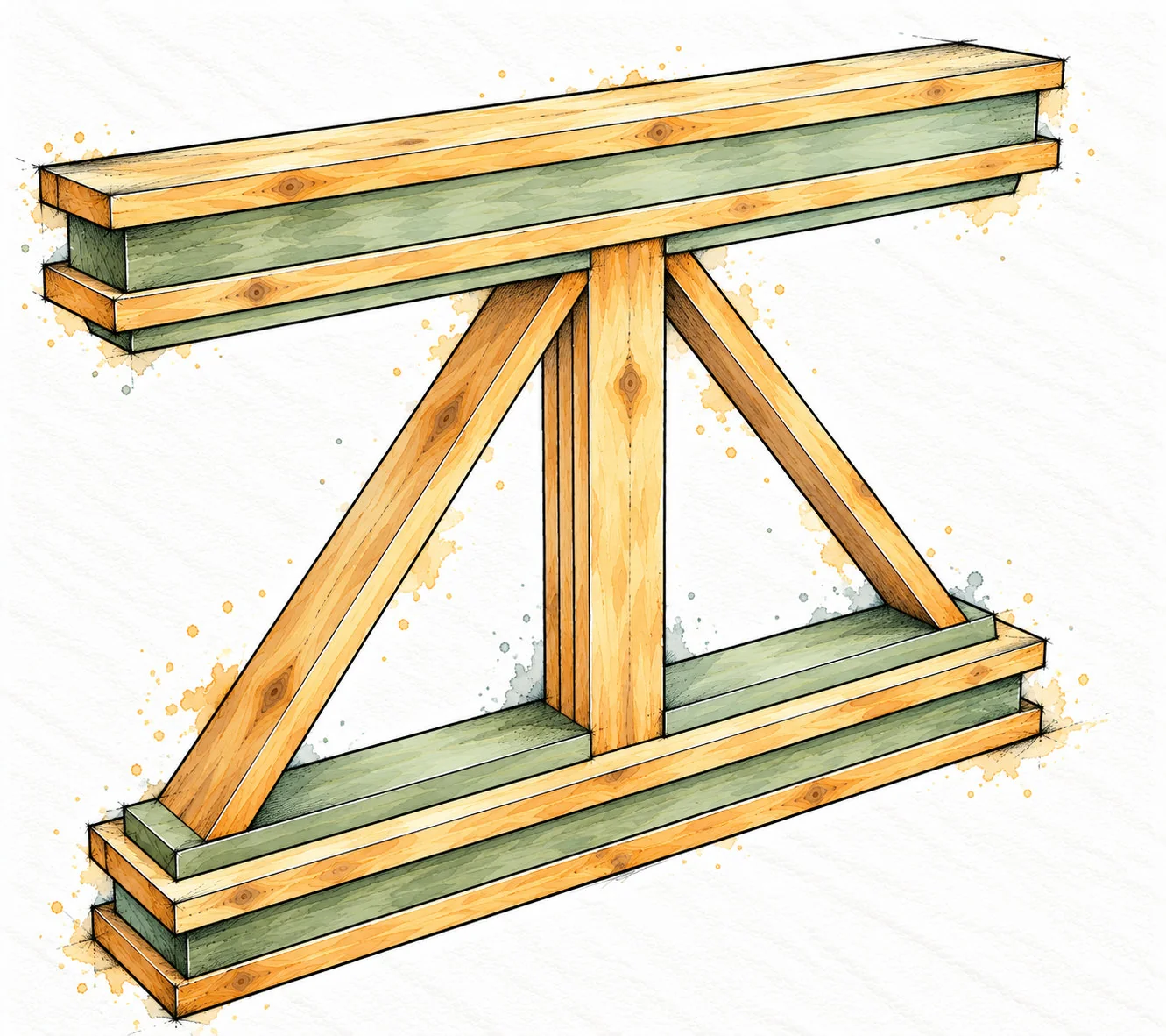
Cut slightly long and trim gradually until both ends seat. The diagonals form an inverted V, from outer lower trim toward the post beneath the upper trim. Glue the contact faces, clamp and use 2 1/2 in (63.5 mm) finish nails without splitting the angled ends.
CHECK BEFORE CONTINUING
Both diagonals must fit without bowing the frame. Retain the small exposed trim toe at each lower outer end.
FINISH 01 / INSPECTION AND INSTALLATION
Prepare the surfaces
Prepare the surfaces · Narrow Truss Console
Fill nail holes and small cosmetic defects with compatible wood filler. Let it dry, then sand flush. Sand with the grain and soften sharp handling edges without rounding away the crisp apron miters. Remove dust before applying finish.
FINISH AND SAFETY CHECK
Inspect every joint first. Filler is not a repair for a loose joint, split brace or poorly fitted miter.
FINISH 02 / INSPECTION AND INSTALLATION
Apply a compatible finish
Apply a compatible finish · Narrow Truss Console
Test your chosen primer, paint or stain-and-clear-coat system on an offcut. Apply the products in their specified order and follow the labels for ventilation, coverage, drying, sanding between coats and full cure time. The white finish shown is an option, not a required product.
FINISH AND SAFETY CHECK
Keep the work area ventilated. Handle and dispose of oil- or solvent-soaked materials exactly as their labels direct.
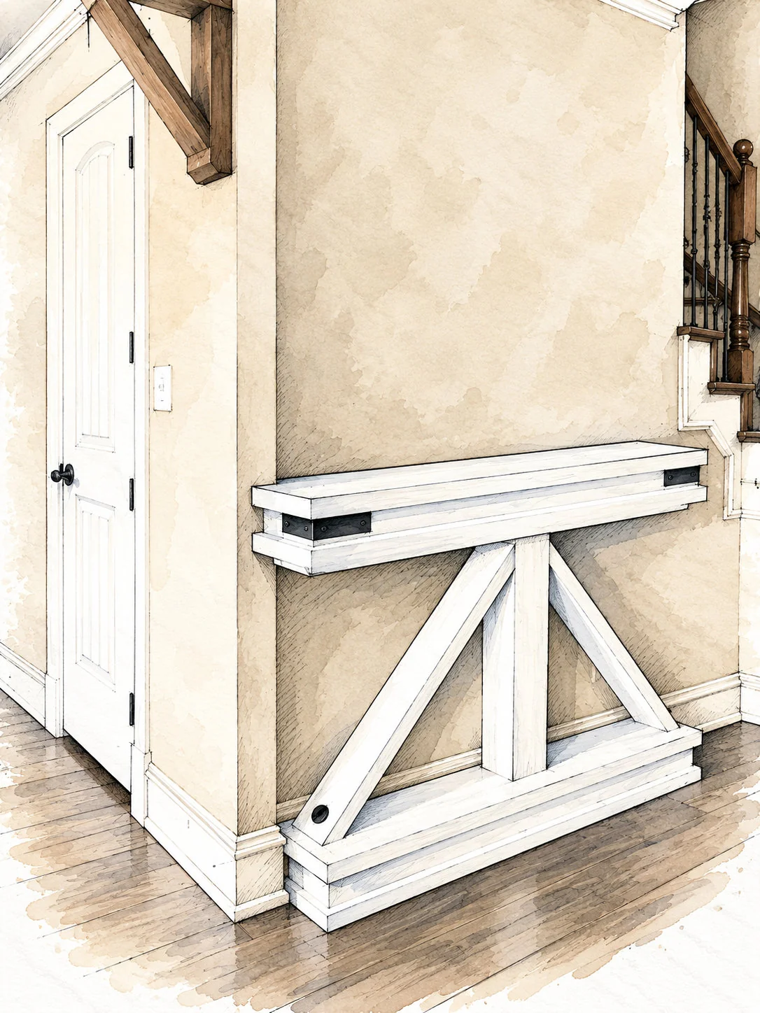
Corner plates and round nail-head accents can provide the dark details shown here. They are optional and nonstructural. Fit them only after confirming the finish and hardware instructions are compatible. Use the hardware manufacturer’s specified fasteners and avoid concealed assembly screws.
FINISH AND SAFETY CHECK
Decorative plates and nail heads do not replace glue joints, structural screws or the separate wall restraint.
FINISH 04 / INSPECTION AND INSTALLATION
Secure the console against tipping
Secure the console against tipping · Narrow Truss Console
Before use, secure the console to suitable structural wall framing or masonry with a compatible furniture anti-tip restraint. Select the restraint and wall fasteners for the actual construction and install them according to their instructions. Locate hidden pipes and wiring before drilling; use a competent installer if unsure.
FINISH AND SAFETY CHECK
Do not rely on drywall alone, baseboard contact or decorative corner hardware. Keep children from pulling or climbing on the console.
FINISH 05 / INSPECTION AND INSTALLATION
Inspect and care for the console
Inspect and care for the console · Narrow Truss Console
Check that the base rests evenly, all joints are firm, no fastener points protrude and the finish has fully cured. Recheck the wall restraint and joints periodically. Lift the console with help rather than dragging it. Wipe spills promptly and follow the finish manufacturer’s cleaning advice.
FINISH AND SAFETY CHECK
No tested load rating is provided. Do not sit, stand or climb on this console, and avoid heavy or unstable displays.
REFERENCE / CUTTING MAP
Stock allocation and profiles
Stock allocation and profiles · Narrow Truss Console
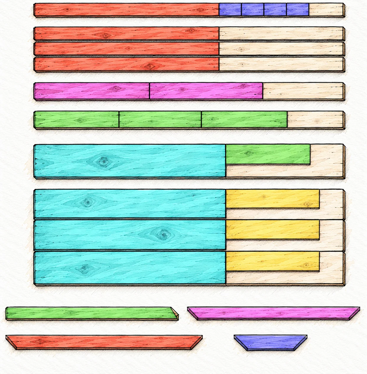
Top four rows: 2×4 stock for C and D. Middle two rows: 2×6 stock for F and three E. Bottom four rows: 2×10 stock for B, three A and the fourth E. Pale areas are unused offcuts.
Bottom profiles, left to right: E 30° with 3/4 in (19.1 mm) short edge; F 45° reference ends; C 45° miters; D 45° miters. Use the typed cut list on page 6, allow for kerf, and fit F to the actual frame.
STEP 01 / ASSEMBLY DIAGRAM
Check the laminated leg
Check the laminated leg · Narrow Truss Console
Three equal laminations form one post. The near end shows three layers and two seams; the long grain runs along the post.
Dimension and joint check
Each A: 30 × 5 × 1 1/2 in 762.0 × 127.0 × 38.1 mm Completed post: 30 × 5 × 4 1/2 in 762.0 × 127.0 × 114.3 mm
CHECK BEFORE CONTINUING
Keep all layers flush. Glue plus 2 1/2 in (63.5 mm) finish nails joins them.
STEP 02 / ASSEMBLY DIAGRAM
Check panel centering
Check panel centering · Narrow Truss Console
Both views show the same joint: the full assembly at left and the panel underside at right. Mark the panel center before attaching it.
Dimension and joint check
Panel center: 29 3/4 in (755.7 mm) from either end Depth center: 4 1/2 in (114.3 mm) from either long edge Panel: 59 1/2 × 9 in (1511.3 × 228.6 mm)
CHECK BEFORE CONTINUING
Glue and 3 in (76.2 mm) screws pass through the panel into the post end.
STEP 03 / ASSEMBLY DIAGRAM
Check the I shaped frame
Check the I shaped frame · Narrow Truss Console
One panel is fixed to each end of the center post. Both panels are single boards at this stage; neither apron has been added.
Dimension and joint check
Panel edges must be parallel and aligned. The 5 in (127.0 mm) post width runs along the long panel axis. The 4 1/2 in (114.3 mm) post depth runs across it.
CHECK BEFORE CONTINUING
Check square in both directions. A twisted post or rotated panel will make later fitted pieces unreliable.
STEP 04 / ASSEMBLY DIAGRAM
Check the two apron frames
Check the two apron frames · Narrow Truss Console
Make two matching open rectangles. The four miters meet at the corners; pocket holes belong on the inner faces, directed toward one panel-contact edge.
Dimension and joint check
Outside: 57 1/2 × 7 in (1460.5 × 177.8 mm) Height: 3 in (76.2 mm) Inside, with 1 1/2 in stock: 54 1/2 × 4 in 1384.3 × 101.6 mm
CHECK BEFORE CONTINUING
Compare corner-to-corner diagonals and keep the frames flat. There are no interior crosspieces.
STEP 05 / ASSEMBLY DIAGRAM
Check the lower apron inset
Check the lower apron inset · Narrow Truss Console
The console is upside down. The frame rests on the lower panel, still open. The circular detail shows the panel extending beyond the apron on both adjacent sides.
Dimension and joint check
Inset from all four panel edges: 1 in (25.4 mm) Pocket-hole setting: 1 1/2 in (38.1 mm) Pocket screws: 2 1/2 in (63.5 mm)
CHECK BEFORE CONTINUING
Measure the inset before and after tightening. The pocket holes are recesses, not pegs or added supports.
STEP 06 / ASSEMBLY DIAGRAM
Check the lower sandwich
Check the lower sandwich · Narrow Truss Console
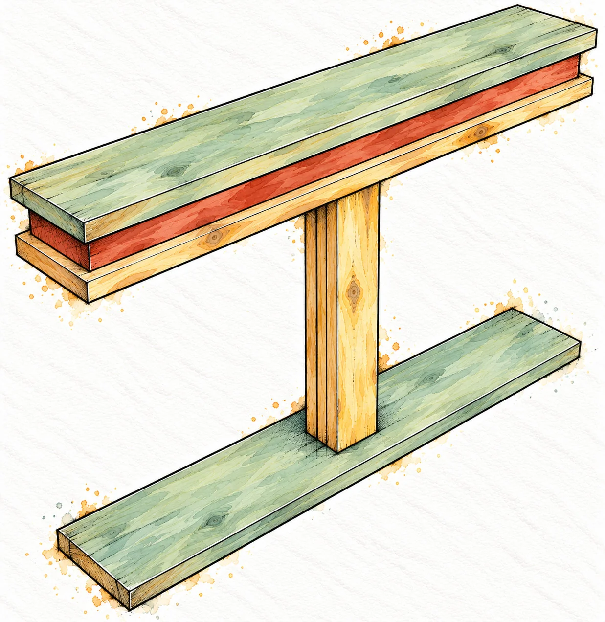
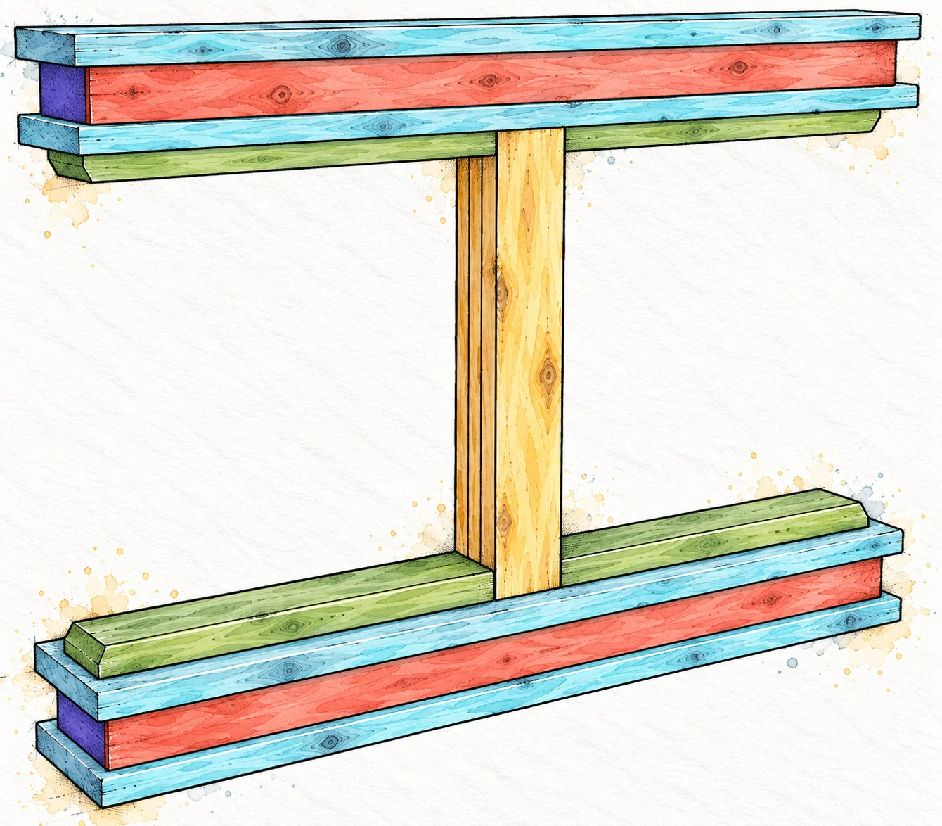
Still upside down, the lower box now has a cap. The opposite end remains one single panel attached to the center post.
Dimension and joint check
Layer height: 1 1/2 + 3 + 1 1/2 = 6 in 38.1 + 76.2 + 38.1 = 152.4 mm Fastening: 2 in (50.8 mm) screws through cap into apron
CHECK BEFORE CONTINUING
Both wide panel outlines must align. Avoid driving screws into the hollow space between apron rails.
STEP 07 / ASSEMBLY DIAGRAM
Check the detached cap assembly
Check the detached cap assembly · Narrow Truss Console
The second apron is mounted on the final loose panel. Keep its center open. The inset again shows the panel projection beyond the apron.
Dimension and joint check
Panel projection: 1 in (25.4 mm) on every side Fastening: glue and 2 1/2 in (63.5 mm) pocket screws Next: turn this assembly over onto the upper panel
CHECK BEFORE CONTINUING
Keep pocket holes accessible until the apron is fully fastened to its cap.
STEP 08 / ASSEMBLY DIAGRAM
Check both completed boxes
Check both completed boxes · Narrow Truss Console
Both ends now have a wide panel, an apron and a second wide panel. The center leg remains the only vertical member; horizontal truss trim has not yet been added.
Dimension and joint check
Upper attachment: 2 in (50.8 mm) screws from the accessible underside of the leg-attached panel upward into the apron. Top and bottom box height: 6 in (152.4 mm) each
CHECK BEFORE CONTINUING
Check parallel bases and aligned panel edges before proceeding. Do not add extra posts or crosspieces.
STEP 09 / ASSEMBLY DIAGRAM
Check the four flat trim pieces
Check the four flat trim pieces · Narrow Truss Console
Two strips meet the post at the lower base; two more meet it beneath the upper base. They lie flat, not on edge, and do not cross through the post.
Dimension and joint check
E width: 4 1/2 in (114.3 mm) E length: 26 1/4 in (666.8 mm) Two E lengths + 5 in post = 57 1/2 in (1460.5 mm)
CHECK BEFORE CONTINUING
Keep the trim front and back edges flush with the post depth. Orient the profiled ends outward.
STEP 10 / ASSEMBLY DIAGRAM
Check the fitted truss joints
Check the fitted truss joints · Narrow Truss Console
The two diagonals create an inverted V, not an X. The circular inset shows the lower foot on the horizontal trim with an exposed toe beyond it.
Dimension and joint check
The detail shows a 2 in (50.8 mm) exposed toe reference. F starts from a 36 in (914.4 mm) reference blank. Final diagonal length and contact cuts are fitted to the built opening.
CHECK BEFORE CONTINUING
Dry-fit both sides before gluing or nailing. Do not shorten the frame, add shims or force braces to match a drawing.
FINAL REFERENCE / OVERALL SIZE
Verify the finished dimensions
Verify the finished dimensions · Narrow Truss Console
Dimension Inches Millimeters
Length 59 1/2 1511.3
Depth 9 228.6
Height 42 1066.8
Height check: 6 in lower box + 30 in post + 6 in upper box = 42 in (1066.8 mm). The trim and diagonals fit within the space between the boxes; they do not add to the overall height.
Complete the wall restraint and final inspection before placing anything on the console.
 FREE WOODWORKING PLAN